background image

56

14 Supplement

VEGAPULS 31 • Two-wire 4 … 20 mA/HART

57820-EN-191014

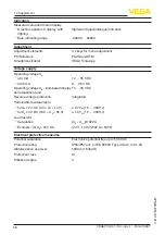
Deviation (according to DIN EN 60770-1)

Process reference conditions according to DIN EN 61298-1


Ʋ Temperature

+18 … +30 °C (+64 … +86 °F)


Ʋ Relative humidity

45 … 75 %


Ʋ Air pressure

860 … 1060 mbar/86 … 106 kPa (12.5 … 15.4 psig)

Installation reference conditions


Ʋ Distance to installations

> 200 mm (7.874 in)


Ʋ Reflector

Flat plate reflector


Ʋ False reflections

Biggest false signal, 20 dB smaller than the useful signal

Deviation with liquids

≤ 2 mm (meas. distance > 0.25 m/0.8202 ft)

Non-repeatability

7)

≤ 2 mm

Deviation with bulk solids

The values depend to a great extent on the application. 

Binding specifications are thus not possible.

0,25 m (0.8202 ft)

10 mm (0.3937 in)

- 10 mm (- 0.3937 in)

2 mm (0.079 in)

- 2 mm (- 0.079 in)

0

1 2

3

Fig. 32: Deviation under reference conditions
1  Antenna edge, reference plane

2  Recommended measuring range

Variables influencing measurement accuracy
Specifications apply to the digital measured value

Temperature drift - Digital output

< 3 mm/10 K, max. 10 mm

Specifications apply also to the current output

Temperature drift - Current output

< 0.03 %/10 K or max. 0.3 % relating to the 16.7 mA 

span

Deviation in the current output due to 

digital/analogue conversion

< 15 µA

Additional deviation through electromagnetic interference


Ʋ According to NAMUR NE 21

< 80 µA


Ʋ According to EN 61326-1

None


Ʋ According to IACS E10 (shipbuilding)/

IEC 60945

< 250 µA

7)

  Already included in the meas. deviation

Summary of Contents for VEGAPULS 31

Page 1: ...Operating Instructions Radar sensor for continuous level measurement VEGAPULS 31 Two wire 4 20 mA HART Document ID 57820 ...

Page 2: ...unting 12 4 1 General instructions 12 4 2 Mounting instructions 13 4 3 Measurement setup Flow 16 5 Connecting to power supply 19 5 1 Preparing the connection 19 5 2 Connecting 20 5 3 Wiring plan 21 5 4 Switch on phase 22 6 Access protection 23 6 1 Bluetooth radio interface 23 6 2 Protection of the parameterization 23 7 Set up with the integrated display and adjustment unit 25 7 1 Adjustment system...

Page 3: ...ssages 44 11 4 Status messages according to NE 107 44 11 5 Treatment of measurement errors 47 11 6 Software update 50 11 7 How to proceed if a repair is necessary 51 12 Dismount 52 12 1 Dismounting steps 52 12 2 Disposal 52 13 Certificates and approvals 53 13 1 Environmental instructions 53 14 Supplement 54 14 1 Technical data 54 14 2 Dimensions 59 14 3 Industrial property rights 60 14 4 Hash func...

Page 4: ...ent ID By entering the Document ID on www vega com you will reach the document download Information note tip This symbol indicates helpful additional infor mation and tips for successful work Note This symbol indicates notes to prevent failures malfunctions damage to devices or plants Caution Non observance of the information marked with this symbol may result in personal injury Warning Non observ...

Page 5: ...es The instrument must only be operated in a technically flawless and reliable condition The operator is responsi ble for the trouble free operation of the instrument When measuring aggressive or corrosive media that can cause a dangerous situation if the instrument malfunctions the operator has to implement suitable measures to make sure the instrument is functioning properly During the entire du...

Page 6: ...n and operation in the USA and Canada This information is only valid for USA and Canada Hence the follow ing text is only available in the English language Installations in the US shall comply with the relevant requirements of the National Electrical Code ANSI NFPA 70 Installations in Canada shall comply with the relevant requirements of the Canadian Electrical Code 2 7 Safety instructions for Ex ...

Page 7: ...mation sheet Emergency unlock codes with Bluetooth access code Bluetooth unlock code Device unlock code The further scope of delivery encompasses Documentation Ex specific Safety instructions with Ex versions If necessary further certificates Note Optional instrument features are also described in this operating instructions manual The respective scope of delivery results from the order specificat...

Page 8: ... TAG1234 1 5 6 2 3 2019 www vega com D 77761 SCHILTACH Made in Germany MWP 3bar 300kPa PVDF Fig 2 Layout of the type label example 1 Instrument type 2 Field for approvals 3 Technical data 4 Number or DataMatrix code for Bluetooth access 5 QR code for device documentation 6 Serial number Move to www vega com and enter in the search field the serial number of your instrument There you can find the f...

Page 9: ...erted into the filling height 3 3 Adjustment On site adjustment of the device is carried out via the integrated display and adjustment unit Note The housing with display and adjustment unit can be rotated 330 for optimum readability and operability without tools Devices with integrated Bluetooth module can be adjusted wirelessly via standard adjustment tools Smartphone tablet iOS or Android operat...

Page 10: ...ort must be carried out in due consideration of the notes on the transport packaging Nonobservance of these instructions can cause damage to the device The delivery must be checked for completeness and possible transit damage immediately at receipt Ascertained transit damage or con cealed defects must be appropriately dealt with Up to the time of installation the packages must be left closed and s...

Page 11: ...092 1 BS 10 ASME B 16 5 JIS B 2210 1984 GOST 12821 80 Welded sockets are used to connect the sensors to the process Threaded adapters enable simple adaptation of sensors with stand ard threaded fittings e g to process side hygiene connections The mounting accessories include e g bracket and mounting bracket and are used for stable mounting of the sensor at the measuring point The parts are availab...

Page 12: ...are Process pressure Process temperature Chemical properties of the medium Abrasion and mechanical influences Protect your instrument against moisture ingress through the following measures Use a suitable connection cable see chapter Connecting to power supply Tighten the cable gland or plug connector Lead the connection cable downward in front of the cable entry or plug connector This applies mai...

Page 13: ... of the radar antenna is the beginning of the measur ing range It is at the same time the reference plane for the min max adjustment see following diagram 1 Fig 6 Reference plane 1 Reference plane When mounting the sensor keep a distance of at least 200 mm 7 874 in from the vessel wall If the sensor is installed in the center of dished or round vessel tops multiple echoes can arise However these c...

Page 14: ...rement is then possible down to the bottom Fig 8 Mounting of the radar sensor on vessels with conical bottom Do not mount the instruments in or above the filling stream Make sure that you detect the product surface not the inflowing product Fig 9 Mounting of the radar sensor with inflowing medium With threaded connection the antenna end should protrude at least 5 mm 0 2 in out of the socket Inflow...

Page 15: ... mm 6 600 mm 23 6 in Note When mounting on longer sockets we recommend carrying out a false signal suppression see chapter Parameter adjustment The mounting location of the radar sensor should be a place where no other equipment or fixtures cross the path of the radar signals Vessel installations such as e g ladders limit switches heating spi rals struts etc can cause false echoes and impair the u...

Page 16: ...tators in motion This ensures that the interfering reflections from the agitators are saved with the blades in different positions Fig 14 Agitators Through the action of filling stirring and other processes in the vessel compact foams which considerably damp the emitted signals may form on the product surface If foams lead to measurement errors you should use the biggest pos sible radar antennas o...

Page 17: ...re The measurement can be individually configured for the respective flume via a PC notebook and PACTware DTM The measurement can be individually configured for the respective flume via a PC notebook and PACTware DTM The following examples serve as an overview for flow measurement 3 4 hmax 90 2 3 1 h max 2 x h max 90 4 2 3 250 mm 9 84 250 mm 9 84 Fig 15 Flow measurement with rectangular flume hmax...

Page 18: ... 20 mA HART 57820 EN 191014 2 3 4 x hmax 90 hmax B 1 250 mm 9 84 Fig 16 Flow measurement with Khafagi Venturi flume hmax max filling of the flume B tightest constriction in the flume 1 Position sensor 2 Venturi flume Khafagi Venturi flume ...

Page 19: ...fluence of additional instruments in the circuit see load values in chapter Technical data Use cable with round cross section for instruments with housing and cable gland To ensure the seal effect of the cable gland IP protection rating find out which cable outer diameter the cable gland is suitable for The instrument is connected with standard two wire cable If electro magnetic interference is ex...

Page 20: ...tection cap as transport protection Note Prior to setup you have to replace this protective cap with an ap proved NPT cable gland or close the opening with a suitable blind plug Note Do not use grease when screwing in the NPT cable gland or a conduit steel pipe Maximum torque see chapter Technical data 5 2 Connecting The voltage supply and signal output are connected via the spring loaded terminal...

Page 21: ...on the max wire cross section under Technical data Electromechanical data Connect the instrument as described in the following wiring plan 5 3 Wiring plan 2 1 2 1 Fig 18 Connection compartment VEGAPULS 31 1 Voltage supply signal output 2 Plug connector for display and adjustment unit Connecting Electronics and connec tion compartment ...

Page 22: ...re 4 20 mA HART 57820 EN 191014 5 4 Switch on phase After connection to the power supply the device carries out a self test Internal check of the electronics Output signal is set to failure The current measured value is then output on the signal cable ...

Page 23: ...tools as all Bluetooth access codes are automatically synchronized when connected to the myVEGA account The emergency Bluetooth unlock code enables Bluetooth communi cation to be established in the event that the Bluetooth access code is no longer known It can t be changed The Emergency Bluetooth unlock code can also be found in information sheet Emergency codes If this document is lost the emerge...

Page 24: ...ger known It can t be changed The emergency device unlock code can also be found on the supplied information sheet Emergency codes If this document is lost the emergency device unlock code can be retrieved from your VEGA contact person after legitimation The storage and transmission of the device codes is always encrypted SHA 256 algorithm Emergency device unlock code ...

Page 25: ...h the integrated display and adjustment unit For these applications the use of PACTware with corresponding DTM is recom mended 1 2 Fig 19 Integrated display and adjustment unit 1 LC display 2 Adjustment keys Key Function Entry to the menu level Jump to selected menu item Edit parameter Select editing position Save value Switching between the individual measured value windows Navigation in the menu...

Page 26: ...nutes after the last pressing of a key an automatic reset to measured value indication is triggered Any values not confirmed with Ο will not be saved 7 2 Measured value and menu item display The measured values are displayed according to the following pres entation 2 3 1 m 2 541 Fig 20 Measured value display example 1 Measured value as bar graph 2 Digital value 3 Unit The menu items are displayed ...

Page 27: ...usher demonstration Silo slender and high Units Distance unit of the device Temperature unit of the instru ment Distance in m Temperature in C Adjustment Max adjustment distance A Min adjustment distance B Max adjustment 15 000 m Min adjustment 0 000 m Menu item Selection Basic settings Displayed value Distance Scaling Scaling size Scaling unit Scaling format 0 correspond to 0 L 100 corre spond to...

Page 28: ...e under Medium Liquid or Bulk solid For Liquid the applications are based on the following characteris tics Storage tank Vessel Large volume Upright cylindrical horizontal round Process measurement conditions Condensation Smooth product surface High requirements on measurement accuracy Slow filling and emptying Properties sensor Low sensitivity to sporadic false echoes Stable and reliable measured...

Page 29: ...easurement conditions Condensation on the sensor Contamination due to buildup such as e g spider webs Partially strongly moved surface dirt and grease deposits on the shaft wall Properties sensor Stable and reliable measured values through frequent averag ing Insensitive in the close range Insensitive to false echoes from buildup on the shaft walls Overflow basin Process measurement conditions Con...

Page 30: ...ate to the application Properties sensor Quick adaptation to changing reflection conditions due to ves sel change required False signal suppression required Gauge measurement in waters Process measurement conditions Slow gauge change Extreme damping of output signal due to wave generation Ice and condensation on the antenna possible Floating debris sporadically on the water surface Properties sens...

Page 31: ...ring reflections due to structured vessel walls or internals Properties sensor Mean averaging High measured value jumps are accepted Heap point measurement profile detection Process measurement conditions Measured value jumps e g by the profile of the heap or trav erses Large angles of repose Measurement near the filling stream Sensor mounting on movable conveyor belts Properties sensor Mean avera...

Page 32: ...ustment enter the distance with full and empty ves sel see the following example 100 0 0 5 m 19 68 5 m 196 9 2 1 3 Fig 22 Parameterisation example Min max adjustment 1 Min level max measuring distance 2 Max level min measuring distance 3 Reference plane The starting point for these distance specifications is always the reference plane i e the lower edge of the sensor Information on the reference p...

Page 33: ...German English Spanish French Chinese Japanese Portuguese Dutch Italian Russian Polish Czech In this menu item you can change the factory preset Bluetooth ac cess code to your personal Bluetooth access code Note The individual preset Bluetooth access code of the device can be found on the supplied information sheet PINs and Codes If this is changed by the user and is no longer available access is ...

Page 34: ...ment via the VEGA Tools app as well as PACTware DTM and other systems is also blocked During a reset parameter settings made by the user are reset to the values of the basic setting or the delivery status see chapter Menu overview 3 Caution For the duration of the reset the set trouble signal is output via the current output Within the context of the asset management function the message Maintenan...

Page 35: ...e signal strength of the level echo above the detection threshold in dB This makes it possible to assess the quality of the measurement The measurement reliability should be at least 20 dB The menu item Sensor information provides the device name and serial number as well as the hardware and software version Measurement reliability Sensor information ...

Page 36: ... Select the requested instrument in the device list For the first connection the operating device and the sensor must authenticate each other After successful authentication the next con nection functions without authentication iOS During the pairing process the following message is displayed Pair ing request Bluetooth e g 12345678 wants to pair with your iPad iPhone Press Pair Android The couplin...

Page 37: ...arameter protection is deactivated by default and can be activated at any time It is recommended to enter a personal 6 digit device code To do this go to menu Extended functions Access protection menu item Protection of the parameter adjustment 8 3 Parameter adjustment The sensor adjustment menu is divided into two areas which are arranged next to each other or one below the other depending on the...

Page 38: ...r After activating the integrated Bluetooth or the Bluetooth USB adapt er devices with Bluetooth are found and created in the project tree 9 2 Connecting Select the requested sensor for the online parameter adjustment in the project tree The window Authentication is displayed For the first connection the operating device and the sensor must authenticate each other After successful authentication t...

Page 39: ...ossible if the parameter protection is deactivated When delivered parameter protection is deactivated by default and can be activated at any time It is recommended to enter a personal 6 digit device code To do this go to menu Extended functions Access protection menu item Protection of the parameter adjustment 9 3 Parameter adjustment For parameter adjustment of the instrument via a Windows PC the...

Page 40: ...essing system PLC Voltage supply 5 Interface adapter VEGACONNECT Note With power supply units with integrated HART resistance internal resistance approx 250 Ω an additional external resistance is not necessary This applies e g to the VEGA instruments VEGATRENN 149A VEGAMET 381 VEGAMET 391 Common Ex separators are also usually equipped with a sufficient current limiting resistance In such cases the...

Page 41: ...iled in a DTM Collec tion The DTMs can also be integrated into other frame applications according to FDT standard Note To ensure that all instrument functions are supported you should always use the latest DTM Collection Furthermore not all described functions are included in older firmware versions You can download the latest instrument software from our homepage A description of the update proce...

Page 42: ...he standard version In the full version there is also an extended print function for complete project documentation as well as a save function for measured value and echo curves In addition there is a tank calculation program as well as a multiviewer for display and analysis of the saved measured value and echo curves The standard version is available as a download under www vega com downloads and...

Page 43: ...eless faults can occur during operation These may be caused by the following e g Sensor Process Voltage supply Signal processing The first measures are Evaluation of fault messages Checking the output signal Treatment of measurement errors A smartphone tablet with the VEGA Tools app or a PC notebook with the software PACTware and the suitable DTM offer you further com prehensive diagnostic possibi...

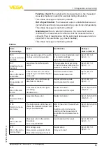
Page 44: ...Check adapt if necessary Current signal greater than 22 mA less than 3 6 mA Sensor electronics defective Replace device or send in for repair de pending on device version 11 4 Status messages according to NE 107 The instrument features self monitoring and diagnostics according to NE 107 and VDI VDE 2650 In addition to the status messages in the following tables there are more detailed error messag...

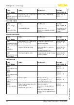
Page 45: ...ifference be tween min and max 10 mm Byte 5 Bit 1 of Byte 0 5 F025 Error in the lineari zation table Index markers are not continu ously rising for example illogical value pairs Check linearisation table Delete table Create new Byte 5 Bit 2 of Byte 0 5 F036 No operable soft ware Checksum error if software up date failed or aborted Repeat software update Send instrument for repair Byte 5 Bit 3 of B...

Page 46: ...te 23 Bit 4 of Byte 14 24 S601 Overfilling Danger of vessel overfilling Make sure that there is no fur ther filling Check level in the vessel Byte 23 Bit 5 of Byte 14 24 S603 Impermissible oper ating voltage Terminal voltage too small Check terminal voltage increase operating voltage Byte 23 Bit 6 of Byte 14 24 Code Text message Cause Rectification DevSpec State in CMD 48 M500 Error in the deliver...

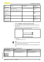
Page 47: ...ement errors The tables below give typical examples of application related meas urement errors The images in column Error description show the actual level as a dashed line and the output level as a solid line 1 2 Level time 0 1 Real level 2 Level displayed by the sensor Note If the output level is constant the cause could also be the fault setting of the current output to Hold value If the level ...

Page 48: ...ate a new false signal suppression Adapt max adjustment Measured value jumps to wards 0 during filling Level time 0 The level echo cannot be distinguished from the false signal at a false signal po sition jumps to multiple echo In case of interferences due to instal lations in the close range Change polarisation direction Chose a more suitable installation po sition Measured value jumps to wards 1...

Page 49: ...iption Cause Rectification Measured value shows a too low or too high level Level time 0 Min max adjustment not correct Adapt min max adjustment Incorrect linearisation curve Adapt linearisation curve Measured value jumps to wards 100 Level time 0 Due to the process the amplitude of the product echo decreases A false signal suppression was not car ried out Carry out a false signal suppression Ampl...

Page 50: ... range during emptying Level time 0 False signal greater than level echo or level echo too small Eliminate false signals in the close range Check Antenna must protrude out of the socket Remove contamination on the antenna Minimize interfering installations in the close range by changing the polariza tion direction After eliminating the false signals the false signal suppression must be de leted Ca...

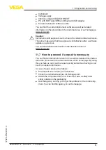
Page 51: ...ftware update is carried out You can find detailed information in the download area at www vega com 11 7 How to proceed if a repair is necessary You can find an instrument return form as well as detailed information about the procedure in the download area of our homepage By doing this you help us carry out the repair quickly and without having to call back for needed information In case of repair...

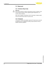
Page 52: ... e g pressure in the vessel or pipeline high temperatures cor rosive or toxic media etc Take note of chapters Mounting and Connecting to voltage supply and carry out the listed steps in reverse order 12 2 Disposal The device is made of recyclable materials For this reason it should be disposed of by a specialist recycling company Observe the ap plicable national regulations ...

Page 53: ...ant duties That is why we have introduced an environment management system with the goal of continuously improving company environmental pro tection The environment management system is certified according to DIN EN ISO 14001 Please help us fulfil this obligation by observing the environmental instructions in this manual Chapter Packaging transport and storage Chapter Disposal Objective and measur...

Page 54: ...nd weights Materials wetted parts Ʋ Ʋ Antenna process fitting PVDF Ʋ Ʋ Process seal FKM Materials non wetted parts Ʋ Ʋ Housing Plastic PBT Polyester Ʋ Ʋ Housing seals Silicone SI 850 R Ʋ Ʋ Cable gland PA Ʋ Ʋ Sealing cable gland NBR EPDM Ʋ Ʋ Blind plug cable gland PA Ʋ Ʋ Inspection window for the indication Polycarbonate Weight 0 7 kg 1 543 lbs Torques Max torque mounting boss 7 Nm 5 163 lbf ft Max...

Page 55: ...9 in Fault signal current output adjustable mA value unchanged 20 5 mA 22 mA 3 6 mA Max output current 22 mA Starting current 3 6 mA 10 mA for 5 ms after switching on Load See load resistance under Power supply Damping 63 of the input variable adjustable 0 999 s HART output values according to HART 7 06 Ʋ Ʋ PV Primary Value Lin percent Ʋ Ʋ SV Secondary Value Distance Ʋ Ʋ TV Third Value Measurement...

Page 56: ...the application Binding specifications are thus not possible 0 25 m 0 8202 ft 10 mm 0 3937 in 10 mm 0 3937 in 2 mm 0 079 in 2 mm 0 079 in 0 1 2 3 Fig 32 Deviation under reference conditions 1 Antenna edge reference plane 2 Recommended measuring range Variables influencing measurement accuracy Specifications apply to the digital measured value Temperature drift Digital output 3 mm 10 K max 10 mm Sp...

Page 57: ...8 2 27 mechanical shock Impact resistance IK07 acc to IEC 62262 Process conditions For the process conditions please also note the specifications on the type label The lowest value amount always applies Process temperature 40 80 C 40 176 F Process pressure 1 3 bar 100 200 kPa 14 5 43 51 psig Electromechanical data Cable entry Ʋ Ʋ Options M20 x 1 5 NPT Ʋ Ʋ Cable gland M20 x 1 5 cable diameter 5 9 m...

Page 58: ... DC Ʋ Ʋ at 20 mA 9 35 V DC Operating voltage UB illuminated display and adjustment unit 15 35 V DC Reverse voltage protection Integrated Permissible residual ripple Ʋ Ʋ for UN 12 V DC 9 V UB 14 V 0 7 Veff 16 400 Hz Ʋ Ʋ for UN 24 V DC 18 V UB 35 V 1 0 Veff 16 400 Hz Load resistor Ʋ Ʋ Calculation UB Umin 0 022 A Ʋ Ʋ Example for UB 24 V DC 24 V 12 V 0 022 A 545 Ω Electrical protective measures Potent...

Page 59: ... wire 4 20 mA HART 57820 EN 191014 14 2 Dimensions VEGAPULS 31 50 mm 1 97 122 mm 4 80 25 mm 0 98 G1 SW 50 ø 58 mm 2 28 ø 77 5 mm 3 05 1 14 NPT R 1 156 mm 6 14 1 2 3 Fig 33 Dimensions VEGAPULS 31 1 Thread G1 2 Thread 1 NPT 3 Thread R1 ...

Page 60: ...у правами на интеллектуальную собственность Дальнейшую информацию смотрите на сайте www vega com VEGA系列产品在全球享有知识产权保护 进一步信息请参见网站 www vega com 14 4 Hash function acc to mbed TLS mbed TLS Copyright C 2006 2015 ARM Limited All Rights Reserved SPDX License Identifier Apache 2 0 Licensed under the Apache License Version 2 0 the License you may not use this file except in compliance with the License You ...

Page 61: ...61 Notes VEGAPULS 31 Two wire 4 20 mA HART 57820 EN 191014 ...

Page 62: ...62 Notes VEGAPULS 31 Two wire 4 20 mA HART 57820 EN 191014 ...

Page 63: ...63 Notes VEGAPULS 31 Two wire 4 20 mA HART 57820 EN 191014 ...

Page 64: ...e of delivery application practical use and operat ing conditions of the sensors and processing systems correspond to the information available at the time of printing Subject to change without prior notice VEGA Grieshaber KG Schiltach Germany 2019 Phone 49 7836 50 0 Fax 49 7836 50 201 E mail info de vega com www vega com ...

Reviews: