background image

VEGADIS

62

47

10

S

upplement

36469

-

EN

-

120329

Summary of Contents for VEGADIS 62

Page 1: ...Operating Instructions VEGADIS 62 Document ID 36469 Indication and adjustment...

Page 2: ...for installation 11 5 Connecting to power supply 5 1 Preparing the connection 13 5 2 Connection technology and steps 14 5 3 Wiring plan 17 5 4 Connection HART standard 17 5 5 Connection HART multidro...

Page 3: ...10 3 Dimensions 48 Safety instructions for Ex areas Please note the Ex speci c safety information for installation and operation in Ex areas These safety instructions are part of the operating instruc...

Page 4: ...el and put into practice by them 1 3 Symbolism used Information tip note This symbol indicates helpful additional information Caution If this warning is ignored faults or malfunctions can result Warni...

Page 5: ...nting or adjustment 2 4 General safety instructions This is a state of the art instrument complying with all prevailing regulations and guidelines The instrument must only be operated in a technically...

Page 6: ...NAMUR recommendations 2 7 Environmental instructions Protection of the environment is one of our most important duties That is why we have introduced an environment management system with the goal of...

Page 7: ...mber 7 Serial number of the instrument 8 Document ID With the serial number of the instrument on the type label you have access to the following data on our homepage l Article number of the instrument...

Page 8: ...tly into the signal cable The housing of VEGADIS 62 contains a lter element for ventilation Hence the insturment is also used for atmospheric pressure compensation of a connected suspension pressure t...

Page 9: ...the control system with the sensor Changes of unit and or measuring range are adapted automatically The parameter adjustment of the sensor is carried out via HART communication During the parameter ad...

Page 10: ...must be left closed and stored according to the orientation and storage markings on the outside Unless otherwise indicated the packages must be stored only under the following conditions l Not in the...

Page 11: ...tion in areas where high humidity is expected e g through cleaning processes or on cooled or heated vessels 4 2 Instructions for installation VEGADIS 62 for wall mounting is supplied with a mounting s...

Page 12: ...der and four screws M5 x 12 as mounting accessory The meas instrument holder is mounted to the socket of VEGADIS 62 1 3 2 Fig 5 VEGADIS 62 for tube mounting 1 4 screws M5 x 12 2 Measuring instrument h...

Page 13: ...not supported The instrument is connected with standard two wire cable without screen If electromagnetic interference is expected which is above the test values of EN 61326 1 for industrial areas scre...

Page 14: ...ground terminal in the sensor and the outer ground terminal on the housing must not be connected to the potential equalisation Information The metal parts of the instrument antenna transmitter concen...

Page 15: ...6 Dismounting of the indicating and adjustment module 3 Loosen compression nut of the cable glands 4 Remove approx 10 cm 4 in of the signal cable mantle strip approx 1 cm 0 4 in insulation from the en...

Page 16: ...terminals by lightly pulling on them 8 Connect the screen to the internal ground terminal connect the outer ground terminal to potential equalisation 9 Attach the indicating and adjustment module aga...

Page 17: ...impedance power supply It is absolutely necessary to install it between voltage supply and the VEGADIS 62 Note If the instrument is powered via a VEGAMET signal conditioning instrument then the commun...

Page 18: ...on resistance in the signal cable is always required for a low impedance power supply It is absolutely necessary to install it between voltage supply and the VEGADIS 62 Note If the instrument is power...

Page 19: ...y with low impedance power supply 4 Voltage supply Processing 1 2 4 3 Fig 12 Installation example with one VEGADIS 62 for several sensors in a Multidrop system 1 Sensor 2 VEGADIS 62 3 HART resistance...

Page 20: ...ion of VEGADIS 62 to a signal conditioning instrument VEGAMET or a four wire sensor with active 4 20 mA output 1 2 3 4 18 17 16 15 1413 1211 10 9 8 7 6 5 N L1 on 1 2 1 2 1 2 3 Fig 14 Connection of the...

Page 21: ...n the HART symbol is displayed The VEGADIS 62 switches to HART mode and and starts operation with the settings accepted from the sensor Note This procedure is repeated whenever the voltage supply is c...

Page 22: ...ed on the LC display The individual keys have the following functions l key One menu higher in the menu system Increase actual value increment l ESC key interrupt input Return to higher ranking menu l...

Page 23: ...the VEGADIS 62 goes automatically to basic mode l If it does not nd a HART sensor within approx 70 s after switching on l If a key was pressed in the switching on phase In basic mode it works exclusiv...

Page 24: ...wards the display behaves passively i e the transmission of additional measured values must be requested from the control system The bargraph is not displayed in HART multidrop 6 3 Parameter descripti...

Page 25: ...gs are possible The unit USER can be individually programmed by the user in the menu Con guration After a reset to a unit supported by the sensor the HART communication is again started Adjustment of...

Page 26: ...justment range 9999 99999 Adjustment of the decimal point for the measuring range of the connected transmitter4 If the unit is set to USER then this menu item is used for free scaling of the indicatio...

Page 27: ...dress must always be set to 0 Adjustment range 0 15 Adjustment of the unit for the digital indication First of all the unit selected in the menu Measurement for example m appears Furthermore the units...

Page 28: ...owever are automatically converted The unit locking functions onyl if the units of measuring range and indication come from the same unit group When connecting a transmitter and its con guration via H...

Page 29: ...range O On Setting the value that triggers the alarm function if it is underrun Adjustment range Initial value of the indicating range up to the adjusted value of the max alarm Setting the value that...

Page 30: ...itches over cyclically between the actual measured value indication period 5 s the min value and the max value indication period each 2 s With the presentation of the max values the displayed unit is...

Page 31: ...rried out The VEGADIS 62 carries out a restart starts again the HART communication and passes over to the measured value indication The following table shows the default values Menu section Menu item...

Page 32: ...racter set is available By pushing the OK key the rst position is selected this position begins to ash With the arrow keys the requested character can be selected By pushing the OK key again the chara...

Page 33: ...you try to use one of the protected functions All functions are accessible after a successful login The logo is carried out in the menu item Logo or automatically after 3 minutes without user activity...

Page 34: ...This menu item is available from software 2 10 It enables the early logout after entering the password Con guration Logout 34 VEGADIS 62 6 Set parameters 36469 EN 120329...

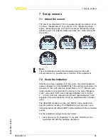
Page 35: ...62 The original sensor value for example in bar with pressure transmitters or in m distance with radar sensors is converted into the unit set in the menu Measure ment menu item Unit and is displayed...

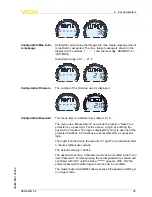
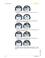
Page 36: ...the menu Measurement menu end MB begin the nal value of the requested scaling 5 Enter in the menu Measurement menu item MB format the requested position of the decimal point The display shows in the...

Page 37: ...red value for the measuring range begin and end are transferred to the sensor when saving Proceed as previously described for a new indication scaling 7 4 PACTware DTM and PLICSCOM With an existing HA...

Page 38: ...38 VEGADIS 62 7 Set up sensors 36469 EN 120329...

Page 39: ...presents the numerical error code The error message is displayed up to the next key pressing The following table shows the error codes and gives information on the failure reason and removal Error cod...

Page 40: ...ssary Current signal greaterthan22mA or less than 3 6 mA l Electronics module in the sensor defecti ve l Exchange the instrument or send it in for repair Depending on the reason for the fault and the...

Page 41: ...back for needed information l Print and ll out one form per instrument l Clean the instrument and pack it damage proof l Attach the completed form and if need be also a safety data sheet outside on t...

Page 42: ...ctronics to be easily separable WEEE directive 2002 96 EG This instrument is not subject to the WEEE directive 2002 96 EG and the respective national laws Pass the instrument directly on to a speciali...

Page 43: ...tion Overcurrent resistance 100 mA Interpolation protection available max current 100 mA Current measurement Measuring range loop current 3 5 22 5 mA8 Deviation9 0 05 of the span Temperature coe cient...

Page 44: ...e 40 80 C 40 176 F Electromechanical data Cable gland 2 x cable entry M20 x 1 5 cable 5 9 mm Spring loaded terminals for wire cross section Massive wire cord 0 2 2 5 mm AWG 24 14 Stranded wire with en...

Page 45: ...out the measured value 15 Read output information To update the scaling of the display after ZERO or SPAN 34 Write damping value 35 Write range values Adjustment of the transmitter scaling 36 Set uppe...

Page 46: ...rough control system After receipt the new scaling is read out with command 15 156 Service command Control calibration parameter adjustment and function test Hart codes of the supported units Unit HAR...

Page 47: ...VEGADIS 62 47 10 Supplement 36469 EN 120329...

Page 48: ...2 72 59 mm 2 32 116 mm 4 57 77 mm 3 03 80 mm 3 15 84 mm 3 31 M20x1 5 M20x1 5 NPT M20x1 5 NPT M20x1 5 NPT M20x1 5 NPT Fig 17 VEGADIS 62 housing versions 1 Plastic housing 2 Stainless steel housing prec...

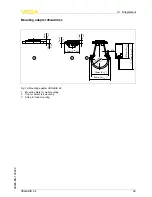
Page 49: ...mm 2 3 4 R32mm 1 17 64 M6 67mm 2 41 64 111mm 4 31 8 3mm 1 8 11mm 7 16 60mm 2 23 64 1 2 3 Fig 18 Mounting adapter VEGADIS 62 1 Mounting plate for wall mounting 2 Clip for carrier rail mounting 3 Strap...

Page 50: ...m Les lignes de produits VEGA sont globalement prot g es par des droits de propri t intellectuelle Pour plus d informations on pourra se r f rer au site http www vega com VEGA lineas de productos est...

Page 51: ...guage 30 Live adjustment span 26 Live adjustment zero point 27 Logout 34 M Measuring range begin 25 Measuring range decimal point 26 Measuring range end 26 Min max memory 30 Modes 9 Basic mode 23 HART...

Page 52: ...vega com Printing date ISO 9001 All statements concerning scope of delivery application practical use and operating conditions of the sensors and processing systems correspond to the information avail...

Reviews: