


16
6 Setup
VEGACAP 35 • Relay (DPDT)
33759-EN-230510
6 Setup
6.1 General information
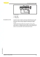
The figures in brackets refer to the following illustrations.
On the electronics module you will find the following display and
adjustment elements:
•
Potentiometer for switching point adaptation
•
DIL switch for mode adjustment - A/B
•
Control lamp
Note:
As a rule, always set the mode with the mode switch (5) before start-
ing setup VEGACAP 35. The switching output will change if you set
the mode switch (5) afterwards. This could possibly trigger other con-
nected instruments or devices.
6.2 Adjustment elements
3
4
5
6
1
2
Fig. 8: Electronics module with relay output
1 Type label
2 Connection terminals
3 Tensile proving ring
4 Control lamp
5 DIL switch for mode adjustment
6 Potentiometer for switching point adaptation
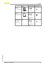
The switching status of the electronics can be checked with closed
housing (only plastic housing), see "
Function table
".
Note:
When placing the housing cover, make sure that the inspection glass
is above the signal lamp (LED) of the electronics module.
Function/Configuration


