


6
.
4
S
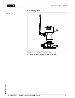
etup procedure
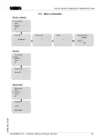
S
etup is comprised mainly of the radio connection adjustment
(
selection radio channel and safe operation
).
T
he selection of
the requested indication value
,
e
.
g
.
in percent
,
linearized
percent or scaled are further adjustment options
(
only when
connecting
VEGA
sensors
).
S
etup of the sensor itself is not
explained in detail here
.
Y
ou can
fi
nd that in the operating
instructions of the respective instrument
.
T
ake note that the
HART
sensor must not operate in multidrop mode
,
it is
absolutely necessary that it be provided with
HART
address
0
(
standard setting
).
A
fter being switched on
,
PLICSRADIO T
61
fi
rst of all carries
out a short self
-
check
.
T
he following steps are carried out
:
l
I
nternal check of the electronics
l
indication of the instrument type
,
fi
rmware version as well
as the instrument
TAG
(
instrument name
)
l
E
nquiry of the sensor input
l
E
stablishment of a radio connection
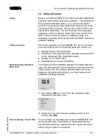
T
he measured value indication displays the digital indication
value
,
the measurement loop designation
(
measurement loop
TAG
)
and the unit
.
T
he actual signal strength can be also
displayed
.
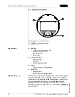
B
y pushing the
[
>
]
key
,
you move between the
individual indicating windows
.
32
.
6
%
TAG
-
N
o
.
1
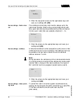
à
B
y pushing
[
OK
]
you move from the measured value
indication to the main menu
.
▶
D
evice settings
D
isplay
D
iagnostics
S
ervice
I
nfo
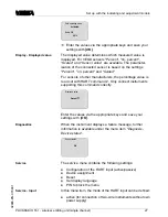
à
S
elect the menu item
"
D
evice settings
"
with
[-
>
]
and
con
fi
rm with
[
OK
]
.
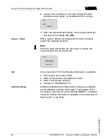
Y
ou can assign an unambiguous name to
PLICSRADIO T
61
via the
D
evice
-
TAG
.
T
his function is recommended when
several instruments are implemented and a good documen
-
tation of larger systems is required
.
S
etup
S
witch on phase
M
easured value indication
/
M
ain menu
D
evice settings
-
D
evice
-
TAG
PLICSRADIO T
61
-
wireless emitting unit
(
single channel
)
25
S
et up with the indicating and adjustment module
32865
-
EN
-
070801


