background image

30

6 Set up with the display and adjustment module

MINITRAC 31 • 4 … 20 mA/HART - four-wire

40447-EN-130430

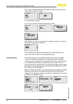
Select "

Determine count rate

" to enter the first point.

The determination of the actual count rate lasts 2 minutes. After the 

count rate has been determined, you can accept the value (ct/s).
Enter now the corresponding level (m).
By doing so, you assign a respective level to the actual count rate.

Accept the value pair with "

OK

".

Depending if you have started with full or empty vessel, you have to 

continue emptying or filling the vessel.
Also carry out such a linearization with several different filling heights 

if you have a linear vessel.

A maximum of 32 linearization points is possible.

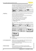
In this menu item you can adjust the damping of the sensor. With 

it you can suppress fluctuations in the measured value indication,  

caused e.g. by an agitated product surface. This time can be between 

1 and 1200 seconds. Keep in mind that also the reaction time in-

creases and the instrument reacts to quick level changes with a delay. 

Generally a time of approximately 60 seconds is sufficient to smooth 

the measured value indication.

Radiation from external sources can influence the measuring result of 

the sensor.
Possible external radiation sources can be, for example, a weld joint 

test on a neighbouring facility or other radiation-based instruments.
An X-ray alarm is triggered if the impulses (ct/s) are more than 25 % 

above the max. value from the linearization table.

This fault message is only outputted for the period of the increased 

X-ray radiation. Then the fault message is automatically reset.
In this menu item you can determine the behaviour of the sensor 

when external radiation sources appear.

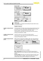
In this menu item you can activate the relay output and determine its 

function as well as the switching points.
When the output of the process values is set, you can choose be-

tween overfill and dry run protection.

The relay outputs of the sensor react accordingly.
You can choose "no" reference value. In this case, the relay output 

operates as fail safe relay.

Caution:

Independent of the selected reference value, the relay will deenergize 

in case of failure.

Setup - Damping

Setup/External radiation 

alarm

Setup/Relay

Summary of Contents for MINITRAC 31

Page 1: ...rk Danehill Lower Earley Reading Berkshire RG6 4UT UK Tel 44 0 118 9311188 Email info able co uk Aberdeen Office Unit 6 Airside Business Park Kirkhill Industrial Estate Dyce Aberdeen AB21 0GT UK Tel 4...

Page 2: ...o power supply 5 1 Preparing the connection 19 5 2 Connection Density mass flow rate measurement 22 5 3 Connection Level detection 24 6 Set up with the display and adjustment module 6 1 Insert display...

Page 3: ...mounting 10 1 Dismounting steps 71 10 2 Disposal 71 11 Supplement 11 1 Technical data 72 11 2 Dimensions 77 Safety instructions for Ex areas Please note the Ex specific safety information for installa...

Page 4: ...hese personnel and put into practice by them 1 3 Symbolism used Information tip note This symbol indicates helpful additional information Caution If this warning is ignored faults or malfunctions can...

Page 5: ...t complying with all prevailing regulations and guidelines The instrument must only be operated in a technically flawless and reliable condition The operator is responsible for the trouble free operat...

Page 6: ...industry in Germany The published NAMUR recommendations are accepted as the standard in field instrumentation The device fulfills the requirements of the following NAMUR recom mendations NE 21 Electr...

Page 7: ...cle number of the instrument HTML Delivery date HTML Order specific instrument features HTML Operating instructions at the time of shipment PDF Order specific sensor data for an electronics exchange X...

Page 8: ...es 3 2 Principle of operation The instrument is suitable for applications in liquids and bulk solids in vessels under difficult process conditions There are application pos sibilities in nearly all ar...

Page 9: ...en the instrument operates as real value correction it transmits the real value to correct another radiation based sensor The measure ment can thus be adapted perfectly to the situation in the vessel...

Page 10: ...ntation and storage markings on the outside Unless otherwise indicated the packages must be stored only under the following conditions Not in the open Dry and dust free Not exposed to corrosive media...

Page 11: ...diation based measurement setup The handling of radioactive material is regulated by law The radiation protection rules of the country in which the system is operated apply first and foremost In Germa...

Page 12: ...reases in proportion to the square of the distance to the radiation source The plant operator must appoint a radiation safety officer with the necessary expert knowledge He is responsible that the rad...

Page 13: ...leaning processes installations on cooled or heated vessels Make sure that all parts of the instrument exposed to the process are suitable for the existing process conditions These are mainly Active m...

Page 14: ...ce container e g VEGASOURCE You can mount the MINITRAC 31 in any position If you have ordered your instrument with a lead cover as a protection against ambient radiation optionally the the sensor is s...

Page 15: ...rent ways to increase the radiated length L of the medium L L L 1 4 a b 2 3 Fig 5 Installation possibilities Density measurement or concentration meas urement 1a Direct radiation Horizontal mounting 1...

Page 16: ...an optional lead ring A later retrofitting of the lead ring is not possible Mass flow rate The mass flow rate can be determined with the MINITRAC 31 in conjunction with a flow meter 1 2 Fig 6 Mass fl...

Page 17: ...on 1 Mounting horizontal 2 Mounting vertical 3 Mounting horizontally at right angles to container Level measurement Residue detection The MINITRAC 31 can be used for residue detection e g in storage t...

Page 18: ...from the heat source Make sure these measures are taken into account already in the plan ning stage If you want to carry out such measures later on contact our specialists to ensure that the accuracy...

Page 19: ...in ensures the seal effect of the cable entry If cable with a different diameter or wire cross section is used exchange the seal or use an appropriate cable connection Free cable glands have n suffic...

Page 20: ...g must not be connected to the potential equalisation Information The metal parts of the instrument are conductively connected with the inner and outer ground terminal on the housing This connection i...

Page 21: ...ng with a small screwdriver the terminal opening is freed When the screwdriver is released the terminal opening closes again 7 Check the hold of the wires in the terminals by lightly pulling on them T...

Page 22: ...tput 4 20 mA HART active 4 Signal output 4 20 mA HART passive 5 Signal input 4 20 mA active sensor 6 Switching input for NPN transistor 7 Switching input floating 8 Transistor output 9 Interface for s...

Page 23: ...sensor 4 Switching input for NPN transistor 5 Switching input floating 6 Transistor output 7 Interface for sensor sensor communication MGC 8 Setting the bus address for sensor sensor communication MGC...

Page 24: ...GC 10 Setting the bus address for sensor sensor communication MGC 3 5 6 7 8 2 1 Fig 15 Adjustment and connection compartment with non Ex instruments and instruments with non intrinsically safe current...

Page 25: ...the bus address for sensor sensor communication MGC 4 5 6 7 8 2 3 4 1 2 1 Fig 17 Adjustment and connection compartment Ex ia with instruments with intrinsically safe current output 1 Terminals for int...

Page 26: ...electronics you can choose any one of four different posi tions each displaced by 90 3 Press the display and adjustment module onto the electronics and turn it to the right until it snaps in 4 Screw h...

Page 27: ...Jump to next higher menu The sensor is adjusted via the four keys of the display and adjust ment module The LC display indicates the individual menu items The functions of the individual keys are show...

Page 28: ...on for example of device status peak value simulation Additional adjustments Instrument unit reset date time copying function Info Instrument name hardware and software version date of manu facture in...

Page 29: ...his menu item you can enter the measuring range min and max process value of the sensor These settings influence the current output of the sensor Enter in the menu window Max process value the max lev...

Page 30: ...ges with a delay Generally a time of approximately 60 seconds is sufficient to smooth the measured value indication Radiation from external sources can influence the measuring result of the sensor Pos...

Page 31: ...etting of the measured min and max temperatures to the actual measured value The following table shows the default values of the instrument The values apply for the application Level First of all you...

Page 32: ...ere can be an increased local dose rate Make sure that the tube is filled even in case of plant downtime or switch the source container off Carry out a setup in the sequence described in the following...

Page 33: ...find this information on the type label of the source container Through this selection the sensitivity of the sensor is adapted perfectly to the isotope The normal reduction of the emitter activity is...

Page 34: ...be automatically deducted from the total pulse rate This means only the component of the pulse rate originating from the source will be displayed The source container must be closed for this setting O...

Page 35: ...sor First of all select the unit of the inside diameter Enter in the menu window Inside diameter the inside diamter of the tube for example in cm If the tube is not radiated with 90 then you have to e...

Page 36: ...t with several points to increase the accuracy of the measurement Note Water has as a known density value of 1 g cm3 Carry out the adjust ment with water if possible Prerequisites The radiation is swi...

Page 37: ...ty measurement by doing this The more linearization points you enter and the higher the difference between the density values the more reliable the measurement Value pairs that are not yet complete e...

Page 38: ...zation point In this menu item you can adjust the damping of the sensor With it you can suppress fluctuations in the measured value indication caused e g by an agitated product surface This time can b...

Page 39: ...ault In this menu item you can define the behaviour of the current output You can specify the current at minimum and maximum density sepa rately Radiation from external sources can influence the measu...

Page 40: ...otection The relay outputs of the sensor react accordingly The following reference values can be selected None Relay operates as fail safe relay Electronics temperature Process value No reference valu...

Page 41: ...module Here you can retrieve the adjustment value of the sensor This is the percentage value of the difference of the min and max adjustment points Delta I The value is an indication for the reliabili...

Page 42: ...tment module In this menu item you can set the actual date and time This parameter is described in the operating instructions manual Display and adjustment module When a reset is carried out all setti...

Page 43: ...or Isotope Cs 137 Applications Density Background radiation 0 ct s Unit of the process value g cm3 Temperature unit C Adjustment min process value 0 500 g cm3 Adjustment max process value 1 500 g cm3...

Page 44: ...djustment the instrument is adapted to the application conditions The parameter adjustment is carried out via an adjustment menu Information In this operating instructions manual the instrument specif...

Page 45: ...adjust the MINITRAC 31 to the integrated isotope in the source container For this purpose check which isotope is integrated in the source container You can find this information on the type label of...

Page 46: ...ct if you want to carry out a single or double point adjustment on the sensor With the double point adjustment the Delta I value is selected auto matically We recommend selecting the double point adju...

Page 47: ...ve selected Single point adjustment as adjustment mode Setup Adjustment mode In this menu item you can adjust at which percentage value of the max pulse rate the sensor should switch over Since in mos...

Page 48: ...adjustment mode setup adjustment mode the Double point adjustment In this menu item you can set the max pulse rate ct s at which the sensor should switch over Empty the vessel until the MINITRAC 31 is...

Page 49: ...l is reached Dry run protection the relay will deenergise safe condition when the min level is reached Make sure that you have selected the correct characteristics See menu item Setup Current output m...

Page 50: ...ed out a single point adjustment this is the entered value With a double point adjustment this is the calculated value The value is an indication for the reliability and reproducibility of the switchi...

Page 51: ...g of the PIN is 0000 This parameter is described in the operating instructions manual Display and adjustment module In this menu item you can set the actual date and time This parameter is described i...

Page 52: ...application Depending on the instrument version not all menu items may be available or they may be differently assigned Menu Menu item Default value Adjustment Measurement loop name Sensor Isotope Cs...

Page 53: ...instructions manual Display and adjustment module 6 6 Parameter adjustment X ray alarm X ray radiation for example cause with weld joint tests can influence your measured values unnoticeably Hence it...

Page 54: ...for the display If not you can change the language in the menu item Display Language Start with the setup of MINITRAC 31 In the main menu point Setup the individual submenu points should be selected s...

Page 55: ...ctionality when the output is active again With this menu item you safeguard the sensor parameters against unauthorized or unintentional modifications This menu item is described in the operating inst...

Page 56: ...value display Diagnosis Information for example of device status peak value simulation Additional adjustments Instrument unit reset date time copying function Info Instrument name hardware and softwar...

Page 57: ...e correction With this menu item you safeguard the sensor parameters against unauthorized or unintentional modifications This menu item is described in the operating instructions manual Display and ad...

Page 58: ...nction can also be used to transfer settings from one instru ment to another instrument of the same type If it is necessary to exchange a sensor the display and adjustment module is inserted into the...

Page 59: ...interface adapter VEGACONNECT 3 is not suitable for connec tion to the sensor 1 5 2 4 3 O PE N TWIST USB LO C K Fig 22 Connecting the PC via HART to the signal cable 1 MINITRAC 31 2 HART resistance 2...

Page 60: ...PACTware and a suitable instrument driver DTM according to FDT standard are required The up to date PACTware version as well as all available DTMs are compiled in a DTM Collec tion The DTMs can also b...

Page 61: ...version In the full version there is also an extended print function for complete project documentation as well as a save function for measured value and echo curves In addition there is a tank calcu...

Page 62: ...escriptions as Enhanced Device Description EDD are available for DD adjustment programs such as for example AMS and PDM The files can be downloaded at www vega com downloads under Software 8 2 Field C...

Page 63: ...check Out of specification Maintenance requirement and explained by pictographs 4 1 2 3 Fig 24 Pictographs of the status messages 1 Failure red 2 Out of specification yellow 3 Function check orange 4...

Page 64: ...lt Error on the current input No valid measured value Connected instruments without function Check current input Check connected instru ments Slaves F016 Adjustment data ex changed Values of the min a...

Page 65: ...iring of the current output Exchanging the electronics F052 Faulty config uration Invalid parameter adjust ment Carry out a reset F066 Faulty adjust ment Adjustment not yet carried out Error during ad...

Page 66: ...dose too high Determine reason for increased radiation F125 Ambient tem perature too high Ambient temperature on the housing outside the specification Cool the instrument or pro tect it with isolating...

Page 67: ...ement errors Further comprehensive diagnostics options offer a PC with the soft ware PACTware and the suitable DTM In many cases the reasons can be determined in this way and faults can be rectified C...

Page 68: ...the switching threshold car ry out a double point adjustment Current sig nal greater than 22 mA or less than 3 6 mA Electronics mod ule in the sensor defective Note error messages on the display and...

Page 69: ...or mation of the procedure under www vega com downloads and Software You can find information about the installation in the download file Caution Instruments with approvals can be bound to certain sof...

Page 70: ...gnostics and service MINITRAC 31 4 20 mA HART four wire 40447 EN 130430 Please ask the agency serving you for the address of your return shipment You can find the competent agency on our website www v...

Page 71: ...panies We use recyclable materials and have designed the parts to be easily separable Correct disposal avoids negative effects on humans and the environ ment and ensures recycling of useful raw materi...

Page 72: ...cs 4 1 kg 9 lbs Stainless steel housing with electron ics 9 1 kg 20 1 lbs Max torque mounting screws fastening lugs on the sensor housing 50 Nm 36 88 lbf ft Max torque for NPT cable glands and Conduit...

Page 73: ...Potential separation Available Signal resolution 0 3 A Failure signal current output adjustable 22 mA 3 6 mA Max output current 22 mA Starting current 3 6 mA Load 4 20 mA HART active 500 4 20 mA HART...

Page 74: ...iable Automatically HART output values PV Primary Value X ray alarm SV Secondary Value Electronics temperature Output variable Real value correction Output signals 8 16 mA HART active 8 16 mA HART pas...

Page 75: ...ar 86 106 kPa 12 5 15 4 psig Repeatability 0 1 Deviation with bulk solids The values depend to a great extent on the application Binding specifications are thus not possible Deviation under EMC influe...

Page 76: ...1 5 2 x cable gland M20 x 1 5 cable 6 12 mm 4 x blind plug M20 x 1 5 Included 1 x cable gland M20 x 1 5 NPT 5 x closing cap red NPT Included 3 x cable gland NPT cable 6 12 mm 4 x blind plug NPT Spring...

Page 77: ...ction class I Approvals Instruments with approvals can have different technical data depending on the version For that reason the associated approval documents of these instruments must be carefully n...

Page 78: ...130430 Aluminium and stainless steel housing 242 5 mm 9 55 54 5 mm 2 15 9 mm 0 35 9 mm 0 35 175 mm 6 89 90 mm 3 54 100 mm 3 94 143 5 mm 5 65 169 mm 6 65 116 5 mm 4 59 119 mm 4 69 M20x1 5 NPT Fig 25 Al...

Page 79: ...79 11 Supplement MINITRAC 31 4 20 mA HART four wire 40447 EN 130430 MINITRAC 31 57 mm 2 24 242 5 mm 9 55 Fig 26 MINITRAC 31 L Measuring range...

Page 80: ...erbliche Schutzrechte N here Informationen unter www vega com Les lignes de produits VEGA sont globalement prot g es par des droits de propri t intellec tuelle Pour plus d informations on pourra se r...

Page 81: ...Device name 44 53 Device settings Copy 44 53 Displayed value 41 49 E EDD Enhanced Device Description 62 Error messages 63 F Fault rectification 67 Functional principle 9 G Grounding 19 H Handling per...

Page 82: ...47 EN 130430 S Sensor status 41 50 Service hotline 68 Shielding 19 Simulation 41 50 Source container 11 Status messages 63 Storage 10 T Time 42 51 Type plate 7 U Unit 46 Units 29 34 V Voltage supply 1...

Page 83: ...83 Notes MINITRAC 31 4 20 mA HART four wire 40447 EN 130430...

Page 84: ...of delivery application practical use and operat ing conditions of the sensors and processing systems correspond to the information available at the time of printing Subject to change without prior n...

Reviews: