


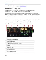
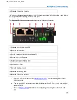
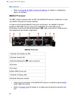
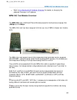

MPA Chassis
83
MPA Chassis
MPA Chassis Overview
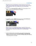
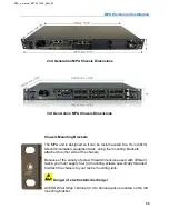
There are currently three generation chassis designs to the MPA system.
The information below describes the features and test module slot locations for each
chassis generation.
for chassis dimensions and installation instruction.
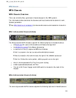
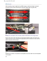
MPA 1st Generation Chassis (5-Slots):
The first generation MPA chassis supports the following high-level chassis features:
•
for user communication and chassis management
•
•
A maximum of five (5) single-slot MPM test modules
Slot 1 is located in the top row above the AM4022 processor
Slot 2 is located in the bottom row to the right of the AM4022 processor
Slot 3 to 5 follow the same pattern, shifting up and over to the right
•
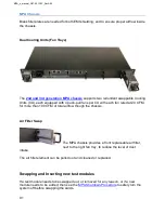
One (1) field replaceable Fan Tray for system cooling
•
A field replaceable/washable Air Filter
•
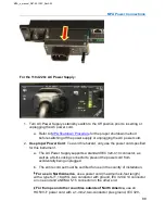
The AC or DC Power Supply and On/Off switch is located on the back of the
chassis
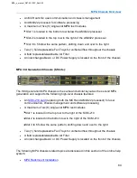
MPA 2nd Generation Chassis (5-Slots):
The second generation MPA chassis supports the following high-level chassis features:
MPA_e_manual_D07-00-129P_RevA00
Summary of Contents for MPA
Page 2: ...MPA_e_manual_D07 00 129P_RevA00...
Page 10: ...MPA_e_manual_D07 00 129P_RevA00...
Page 82: ...MPA_e_manual_D07 00 129P_RevA00...
Page 110: ...MPA_e_manual_D07 00 129P_RevA00...
Page 134: ...MLD Tab 134 100G RS FEC Ethernet 400G RS FEC Ethernet MPA_e_manual_D07 00 129P_RevA00...
Page 255: ...Protocol Tabs 255 MPA_e_manual_D07 00 129P_RevA00...
Page 256: ...OTN Tab 256 MPA_e_manual_D07 00 129P_RevA00...
Page 748: ...MPA_e_manual_D07 00 129P_RevA00...
Page 796: ...MPA_e_manual_D07 00 129P_RevA00...


