background image

FX80 PON Optical Power Meter User Manual 


Page 20 of 38 


The fiber under test must have only one wavelength. If there are several 
wavelengths, the measurement results will NOT be valid. 

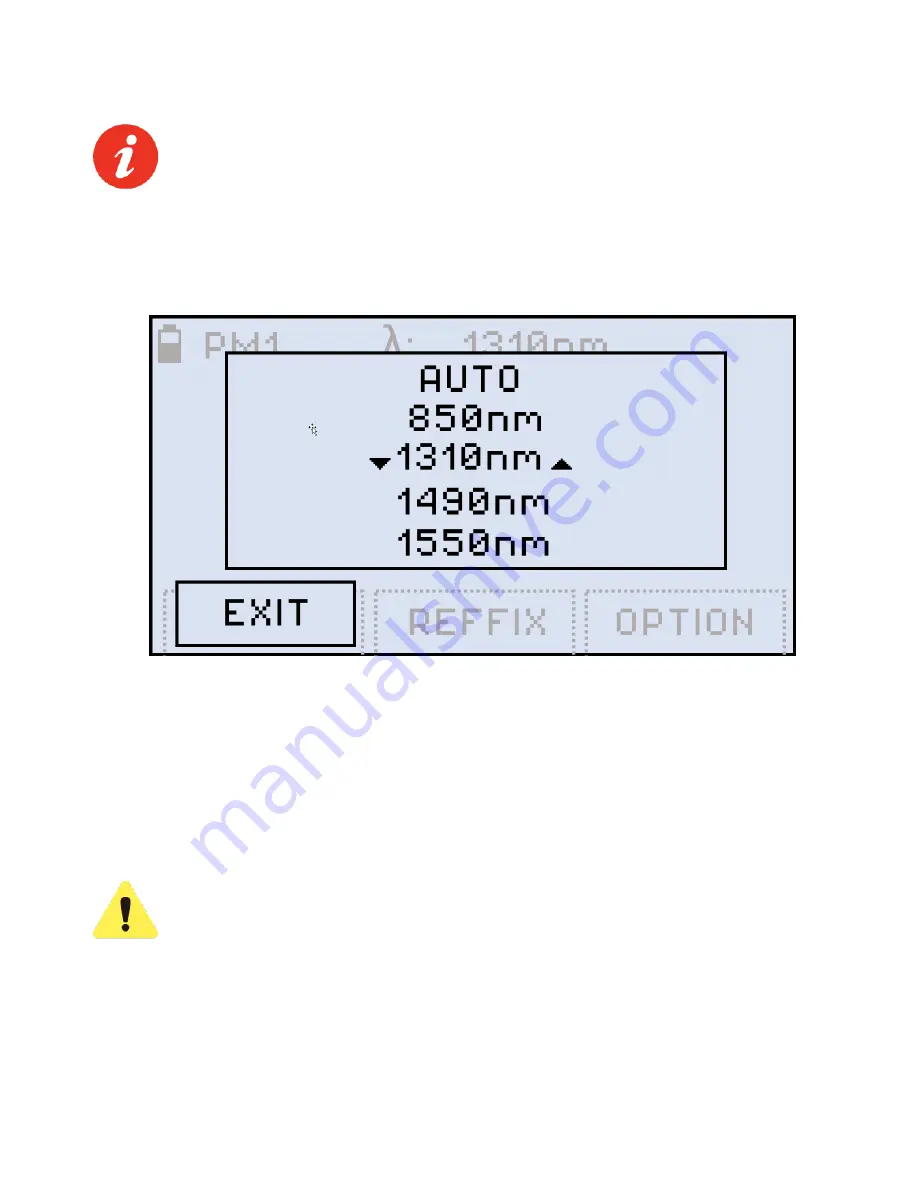
To change the wavelength, press the 

|F1| (WAVE)

 button. The resulting calibrated wavelength 

list is then shown below. 


Selecting a wavelength for PM measurement 


Select a wavelength by pressing the 

|Up|

 and 

|Down|

 buttons, then press the 

|Shift/Enter|


button to confirm the choice. The new wavelength then appears in the top right corner of the 
display. For the previous wavelength to remain effective, select a wavelength and then press 
the 

|F1| (EXIT)

 button. 

If the fiber under test carries a signal with WaveID details, select 

[ AUTO ]

. Then, the FX80 

determines the wavelength automatically. 


If the [ AUTO ] option for a signal without WaveID or modulated is 
selected

, the λ value goes blank and the measurement results are NOT 

valid. 


6.3.1 

Setting Power Reference Level 

To measure the fiber under test span loss, first set a reference level for each test wavelength. 
Set the reference level by pressing the 

|F3| (OPTION) 

button.  


Summary of Contents for FX80 PON

Page 1: ...FX86 CWDM Quad Laser Source User Manual Page 1 of 38...

Page 2: ...shold Profiles for Measurements 14 6 2 2 3 ITU T G 984 2 Standard Pass Fail Thresholds 15 6 2 2 4 Loading the Saved Profile or the Default Profile 16 6 2 3 Performing Optical Power Measurements in PON...

Page 3: ...certain other countries All trademarks or registered trademarks are the property of their respective companies No part of this document may be reproduced or transmitted electronically or otherwise wi...

Page 4: ...angerous situation Make sure that optical sources are inactive before connecting fiber to the test set to avoid skin or eye damage or damage to the unit It is recommended to Deactivate the laser befor...

Page 5: ...the cloud using a Fiberizer Cloud account The operator is assumed to have received basic training in fiber optics and related testing and measurement practices FX80 PON power meters are configured by...

Page 6: ...seconds The display will initially show the VeEX logo current date and time and current mode of operation MODE Select the mode of operation PON Burst PON CW Read optional PM1 optional VFL default is...

Page 7: ...present on active network and 1550 nm optional ONT Connect the FX80 to the fiber from the ONU ONT to measure the upstream optical power level in the PON network for 1310 nm transmission OPM optional...

Page 8: ...and to obtain maximum charge To charge the test unit connect the AC DC adaptor supplied with the unit to the micro USB service port located on the left side of the device The battery charging time dep...

Page 9: ...for 3 seconds 2 Press Shift Enter Down to enter the Settings mode The following parameters can be set Auto Shutdown mode Time Date The test parameter currently selected and available to edit will fla...

Page 10: ...nds After the FX80 reboots reset the date and time see Section 5 2 Setting Date and Time As a result of the reset the threshold values and reference values will be lost These values must be reset Also...

Page 11: ...1000 or 2000 Hz between the wavelength range of 800 1700 nm Select a calibrated wavelength that matches the incoming source wavelength 6 2 PON Power Measurements For best results wait 15 minutes after...

Page 12: ...In addition to measuring the downstream and upstream signal levels the FX80 PON can also be configured to provide Pass Fail P F notifications for each wavelength 6 2 2 1 Creating User Defined P F Thr...

Page 13: ...Burst mode 2 Press F1 P F Setting Pass Fail thresholds 3 Press the Up and Down arrow button to select the wavelength 4 Press Shift Enter to start setting the threshold The corresponding value then sta...

Page 14: ...s for future use save them to a Profile 6 2 2 2 Creating Threshold Profiles for Measurements One P F profile with threshold values can be created and saved in memory for future recall To save the curr...

Page 15: ...eive Power Class A Class B Class C Class A Class B Class C Min Avg Power dBm 0 5 3 21 21 28 Max Avg Power 4 9 7 3 7 8 1 244 Gbs US direction 1310nm ONT ONU Launch Power 1310 OLT Receive Power Class A...

Page 16: ...ile or the Default Profile To load the saved profile or the default profile 1 Enter the Setting Pass Fail thresholds mode by pressing the F1 P F button 2 Scroll down to Load Profile and press the MODE...

Page 17: ...upstream will be seen only if a fiber is temporarily connected to the ONT This may require two patch cords 3 Connect the fiber with 1490 1550 nm downstream traffic to the left side OLT test port Confi...

Page 18: ...measurement results as values If P F thresholds have been set the measurement results are presented as Pass or Fail see example below PON Burst mode measurement results as P F thresholds To switch ba...

Page 19: ...e same measurement 6 3 Broadband Power Measurements Optional The Broadband OPM is an InGaAs detector with a wavelength range from 850 to 1650 nm The displayed power readings can be absolute dBm and wa...

Page 20: ...the choice The new wavelength then appears in the top right corner of the display For the previous wavelength to remain effective select a wavelength and then press the F1 EXIT button If the fiber un...

Page 21: ...command sets the current power value as the reference level Select REF FIX with the cursor and press the Shift Enter button The value onscreen then changes to dB The current reference level value is s...

Page 22: ...N The measurement result is then shown in dB see an example below After selecting this option its name changes onscreen to REF OFF REF command finely adjusts the current reference level Press the Up a...

Page 23: ...ing VFL mode 3 Press the F1 ON button to begin the test Starting VFL testing continuous light 4 To modulate the light 1 or 2 Hz press F2 1Hz or F3 2Hz respectively The pressed button then changes to C...

Page 24: ...FX80 PON Optical Power Meter User Manual Page 24 of 38 VFL testing modulated light 5 To switch from the VFL mode to another mode press the MODE button...

Page 25: ...rs in the top right corner in the Read mode 7 1 Editing Notes to Measurement Results By default every measurement is appended with the COMMENT note where is the index incremented by 1 with every measu...

Page 26: ...symbol in the note select the left arrow and execute the command by pressing the Shift Enter button The command erases symbols to the left of the cursor 5 To clear the whole comment at once press F3 C...

Page 27: ...of the Fiberizer Expert package 8 1 Installing the USB Driver for wired transfer For a PC to work with the FX80 device install the USB driver 1 Plug in the FX80 device to the PC via the supplied micr...

Page 28: ...lling the driver for FX80 4 Define the path to the previously saved downloaded driver and click Next The driver installation starts After the installation is complete a window appears indicating the d...

Page 29: ...led 8 2 Transferring Measurement Results via Cable To transfer measurement results to the PC 1 Launch LTSync and connect the FX80 to the PC via the micro USB cable provided The FX Series devices windo...

Page 30: ...FX80 is connected to PC in LTSync its serial number is recognized by the program 2 To view the measurement results on the PC click the Download button example below The measurement results are presen...

Page 31: ...the fields in the Attributes section see example above Filter the results by test group and or wavelength by selecting the results to work with in the main viewing area To download results for a speci...

Page 32: ...rom the FX80 memory select the Hardware tab and click the Erase all memory button 8 4 Transferring Measurement Results via Bluetooth To transfer measurement results to the PC via Bluetooth the FX80 mu...

Page 33: ...desired device in the drop down list After the FX80 and PC are connected the Bluetooth sign inverts its colors see below FX80 and PC connected shows Bluetooth sign with inverted colors 5 To transfer...

Page 34: ...iberizer Cloud Login screen To register for a Fiberizer Cloud account on the Cloud Storage tab click the Register in Fiberizer Cloud button Alternatively click the Sign up link on the Login screen To...

Page 35: ...2 7654321 to which it uploads the results The results saved in the Fiberizer Cloud account will be accessible to other compatible VeEX devices The status bar at the bottom left shows the status of the...

Page 36: ...ts that the customer elects to replace are returned to VeEX Inc by the customer along with proof of purchase within thirty 30 days of the request by the customer freight prepaid Additionally during th...

Page 37: ...e documented Use of this logo implies that the unit conforms to requirements of European Union and European Free Trade Association EFTA EN61010 1 For a copy of the CE Declaration of Conformity relatin...

Page 38: ...address all stages of network deployment maintenance and field service turn up and integrate service verification features across DSL fiber optics CATV DOCSIS mobile backhaul and fronthaul CPRI OBSAI...

Reviews: