


System Setup Screens
Alpha Keypad Screen
11
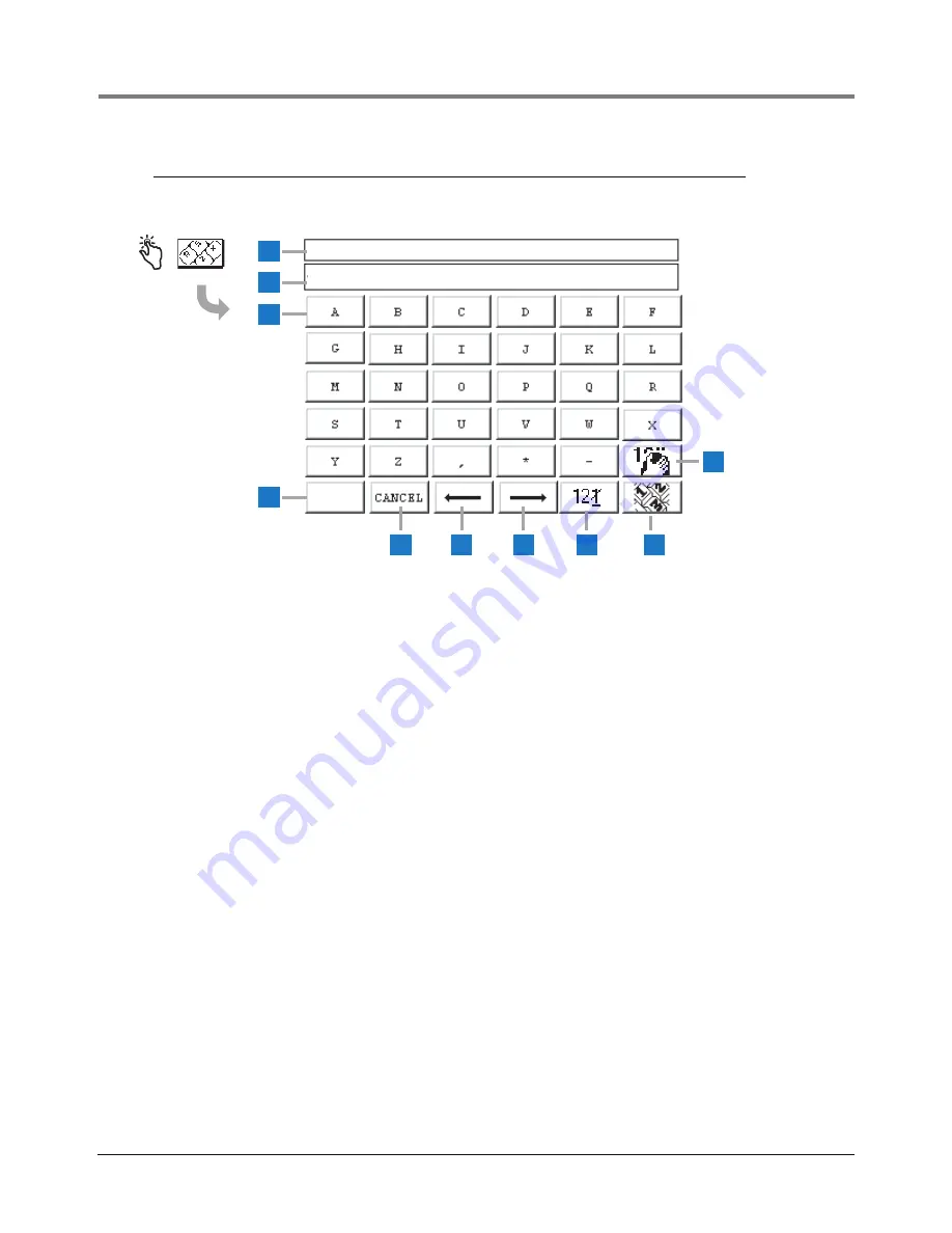
Alpha Keypad Screen
Legend for numbered boxes
1
2
3
4
5
6
7
8
9
10
SAVE
ENTER: STATION HEADER 1
JOHNS MOBIL
1
Displays Title of data to be entered.
2
Data Entered Window displays data entered.
3
Alpha keypad buttons - touch a character button to
place that character in the data entered window (2).
4
Save button - touch to accept entered data and close
Screen.
5
Cancel button - touch to cancel any entry and close
Screen.
6
Cursor left button - touch to move the cursor one
position left in the Data Entered Window (2).
7
Cursor right button - touch to move the cursor one
position right in the Data Entered Window (2).
8
Backspace delete button - touch to delete character in
cursor.
9
Number keypad button - touch to display the Numeric
Keypad Screen.
10
Clear button - touch to clear contents of Data Entered
Window (2).


