Testing Procedures
Manifolded Pumps with Leak Detectors
15
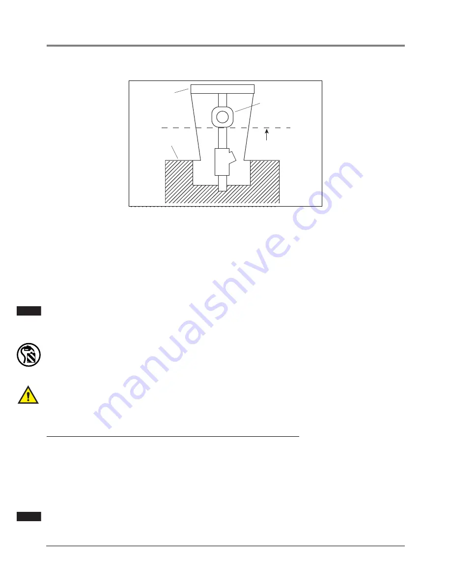
Figure 6. Discharge fluid height limit example
By raising the discharge point of the simulated leak from the FXT above the test area, additional static head is
placed on the LLD. Static head is defined as the pressure exerted on the LLD by the vertical column of fluid
contained within the piping, from the LLD upward to the point of discharge of the leak. By placing the point of
discharge high enough above the island, sufficient static head pressure could be placed upon the LLD to keep
it from entering the leak sensing position. It is assumed that piping from the LLD to the point of discharge is a
continual, gradual, upward or positive run and does not have a negative (declining) run.
For more information on static head effects, please see Red Jacket Service Bulletin 23-5 and 23-18 or the ap-
plication section of the mechanical leak detector manual covering the effects of static head on mechanical leak
detectors.
If the LLD or pumping system operation differs significantly from that described in this manual,
see leak detector manual #5191 and/or Petroleum Products Service Manual #5190, for possible
causes and solutions.
3.
Plug the FXT into the Snap-Tap on the dispenser shear valve as shown in Figure 5 on page 14.
CAUTION! To avoid product spillage, assure the discharge is directed into a suitable container.
4.
A leak check may now be performed by following “Simulated Leak Test - 4 Step Test” on page 7. In this case,
product is not being returned directly to the tank via the Snap-Tap fitting on the pump but is collected in the
container.
Snap Tap connectors shall not be left permanently installed into the impact/shear valves and must be
removed upon completion of testing.
Manifolded Pumps with Leak Detectors
For manifolded systems that have two LLDs on a single line and the pumps operate simultaneously, testing must
be performed at the impact valve, as shown in Figure 5.
The minimum leak detectable will be the sum of the two LLD’s capabilities; typically 6 - 7 gph at 10 psi (23-26 lph
at 69 kPa).
If the minimum leak detectable is unacceptable, the LLDs may be tested individually by having only one pump
come on during the test. This will help in determining which LLD is causing the unacceptable rate.
Pumps must be activated simultaneously in manifolded systems. If they alternate, LLDs cannot be
accurately tested.
Dispenser
Grade
Solenoid
Do not discharge
fluid above this line
rj\fxt1.eps
NOTE
G
A
S
NOTE


