background image

Force Imaging

Force Calibration (TappingMode)

232

Dimension 3100 Manual

Rev. D

13.5.3 High Contact Force

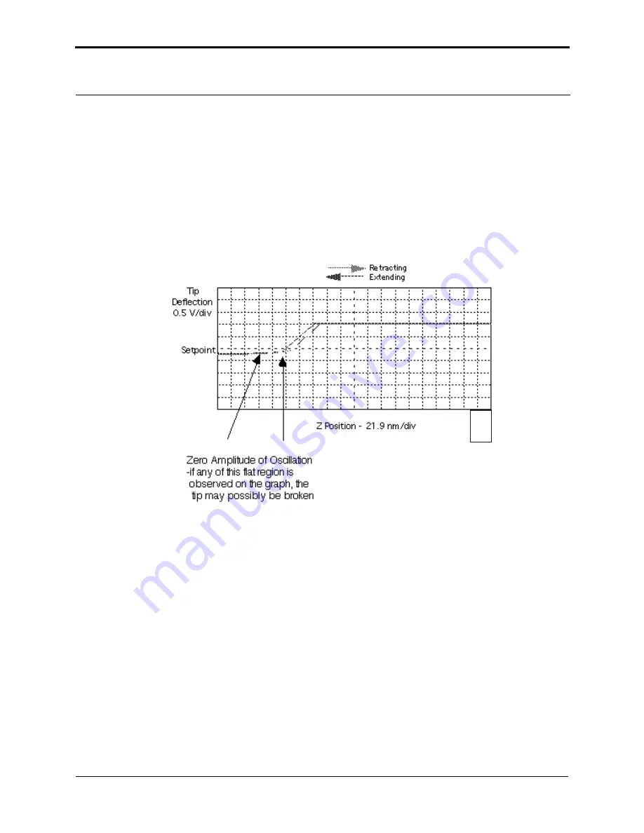
Figure 13.5c

 shows a curve produced when the tip pushes too far into the sample. The flat portion 

on the left side of the amplitude curve in 

Figure 13.5c

 occurs because the tip is so close to the 

surface that it no longer vibrates. As the piezo extends the tip further, the amplitude of vibration 
does not change because the tip is always in contact with the sample surface. The contact force is 
very high due to the stiffness of the TappingMode cantilevers. The tip may shatter if deflection 
continues.

Figure 13.5c   

Amplitude Force Plot with High Contact Force

You can avoid this situation by using triggers (see 

Section 13.3.5

) or by reducing the value of 

scan start

 until there is no flat portion on the left side of the curve. Rapidly increasing the value of 

Z scan start

 is dangerous because the total oscillation amplitude of the cantilever is small relative 

to the total Z travel of the long-range scanner.

13.5.4 Tip Selection

You may use virtually any TappingMode tip to obtain TappingMode force plots; however, the 
ultimate choice depends upon the delicacy of the sample and the magnitude of the forces to be 
gauged. Longer cantilevers have lower spring constants (i.e., they are more pliant) and therefore 
offer greater sensitivity for most samples. Shorter cantilevers afford better control when gauging 
strong attractive forces and are less prone to entrapment by surface tension forces. Sharper tips are 
more likely to plastically deform the sample, and are less sensitive to adhesive forces, than tips that 
are more blunt. Experiment to determine the tip that best meets your needs.

3536

Summary of Contents for Dimension 3100

Page 1: ...R Approval D 03 09 04 All N A C Kowalski C 05 15 03 Fluid Cell N A L Burrows B 06 01 00 All 313 A Varbel A 08 25 97 Released N A M Leilani Copyright 2004 Veeco Instruments Inc All rights reserved Dimension 3100 Manual NanoScope Software Version 5 004 320 000 standard 004 320 100 cleanroom ...

Page 2: ...ed reproduced or translated into another language without prior written consent Copyright Copyright 2004 Veeco Instruments Inc All rights reserved Trademark Acknowledgments The following are registered trademarks of Veeco Instruments Inc All other trademarks are the property of their respective owners Product Names NanoScope MultiMode Dimension BioScope Atomic Force Profiler AFP Dektak Software Mo...

Page 3: ...9 1 3 3 Stage System 9 1 3 4 Dimension SPM Head 9 1 3 5 Cantilever Holder 13 1 3 6 Video Zoom Microscope 14 1 4 Sample Size Handling 15 1 5 Facilities Specifications 16 1 6 Applications 16 1 7 Maintenance and Troubleshooting 16 Chapter 2 Safety 17 2 1 Safety Requirements 19 2 2 Safety Precautions 20 2 2 1 General Operator Safety 20 2 2 2 Microscope 23 2 2 3 Sample Safeguards 26 2 3 Ergonomics 26 2...

Page 4: ... Facilities Requirements 41 3 3 Acoustic Vibration Isolation Systems 42 3 3 1 IS3K 2 Dimensions Utilities and Clearance 42 3 3 2 VT 103 3K Dimensions Utilities and Clearance 45 3 3 3 VT 102 Dimensions and Utilities 46 3 3 4 Computer Controller Facility Requirements 47 3 3 5 ELCON Console 48 3 4 Facilities Requirements Summary 49 3 5 Acoustic Vibration Specifications 50 3 6 General Facilities Guide...

Page 5: ...bstrates 93 6 2 1 Tip Shape of Silicon Nitride Probes 96 Chapter 7 Head Probe Sample Preparation 99 7 1 System Information 100 7 1 1 Mouse versus Trackball 100 7 1 2 Motor Interlock 100 7 1 3 Laser Requirements 101 7 2 Basic AFM Operation 102 7 2 1 Select the Microscope 102 7 2 2 Select Mode of Operation 102 7 2 3 Prepare the Cantilever Holder 102 7 2 4 Load the Cantilever Holder 103 7 2 5 Remove ...

Page 6: ...ings 128 8 3 3 Scan Size and Scan Rate 129 8 3 4 Setpoint 129 8 3 5 Lowpass Filter 129 8 3 6 Highpass Filter 129 8 4 Force Calibration Mode 130 Chapter 9 TappingMode AFM 131 9 1 Principles of TappingMode 132 9 2 Basic TappingMode AFM Operation 133 9 2 1 Select Mode of Operation 133 9 2 2 Head Cantilever and Sample Preparation 134 9 2 3 Align Laser 134 9 2 4 Adjust Photodetector 134 9 2 5 Locate Ti...

Page 7: ...10 5 Operating Principles 157 10 5 1 Clean Fluid Cell and Protective Skirt 157 10 5 2 Select Mode of Operation 157 10 5 3 Load the Probe 157 10 5 4 Install the Fluid Tip Holder 158 10 5 5 Install the Protective Skirt 159 10 5 6 Align Laser 159 10 5 7 False Reflections 160 10 5 8 Load Sample 160 10 5 9 Lower Probe into Fluid 162 10 5 10 Readjust Laser Alignment 162 10 5 11 Adjust Photodetector 162 ...

Page 8: ...5 12 1 Introduction 195 12 2 Basic LFM Operation 196 12 3 Advanced LFM Operation 197 12 3 1 Scan Direction 197 12 3 2 Tip selection 198 12 3 3 Understanding the LFM Signal 198 12 3 4 Understanding the Color Scale 199 12 3 5 Using TMR Voltage to Measure Friction 200 12 3 6 Enhancing the LFM Data by Subtracting Two Images 200 12 3 7 Height Artifacts in the Signal 201 Chapter 13 Force Imaging 203 13 ...

Page 9: ...Chapter 14 Interleave Scanning 247 14 1 Preface Interleave Scanning LiftMode 248 14 2 Interleave Mode Description 249 14 3 LiftMode Description 250 14 4 Operation of Interleave Scanning LiftMode 250 14 5 Use of LiftMode with TappingMode 251 14 5 1 Main Drive Amplitude and Frequency selection 251 14 5 2 Setpoint Selection 252 14 5 3 Interleave Drive Amplitude and Frequency Selection 252 14 5 4 Ampl...

Page 10: ...e Detection 293 16 3 EFM Troubleshooting Pointers 295 16 3 1 Use Low Setpoint When Tapping in Electric Field 295 16 3 2 Verify Electric Field at Surface 295 16 3 3 Fine Tune Lift Scan Height 295 16 3 4 Fine Tune Interleave Drive Amplitude 295 16 3 5 Optimize Tune in Vicinity of Surface 295 16 3 6 Optimize Tune in Interleave 296 16 3 7 If Voltage is Needed Use Analog 2 When Possible 296 16 3 8 Try ...

Page 11: ...Size 329 17 7 5 Measure Vertically at 150V Scan Size 330 17 7 6 Change Scan angle and Repeat Calibration Routines 330 17 8 Calibrating Z 331 17 8 1 Engage 331 17 8 2 Capture and Correct an Image 332 17 8 3 Measure Vertical Features 333 17 8 4 Correct Z Sensitivity 335 17 8 5 Recheck Z axis Measuring Accuracy 335 17 8 6 Calculate Retracted and Extended Offset Deratings 335 Chapter 18 Maintenance Tr...

Page 12: ...xii Dimension 3100 Manual Rev D ...

Page 13: ... 13 Figure 1 3f Fluid Cell Cantilever Holder 14 Chapter 2 Safety 17 Figure 2 1a Safety Symbols Key 19 Figure 2 5a Dimension 3100 SPM Footprint 27 Figure 2 8a Log into Windows NT 33 Figure 2 8b Logon Window 34 Figure 2 8c Select the NanoScope Icon 34 Figure 2 8d Select the Realtime Icon 34 Figure 2 8e Status Panel 35 Figure 2 9a Laser Explanatory Label 36 Figure 2 9b Laser Warning Label 36 Figure 2...

Page 14: ...Figure 4 4c NanoScope IIIa Controller rear view 63 Figure 4 4d Dimension 3100 Controller rear view 64 Figure 4 4e Dimension 3100 Controller front view 65 Figure 4 4f D3100 Microscope Electronics Box rear view 66 Figure 4 4g Vacuum Power Switch 67 Figure 4 4h Cable Clamp 67 Chapter 5 Stage System 69 Figure 5 1a Stage X Y Axis Orientation 71 Figure 5 2a Stage Load Unload Prompt 72 Figure 5 2b Moving...

Page 15: ... Cantilever Holder Stand top view 103 Figure 7 2c Standard AFM Cantilever Holder 104 Figure 7 2d SPM Head Dovetail and Signal Connector 105 Figure 7 2e Dimension Head Laser Control Knobs 107 Figure 7 2f Etched Silicon Tip Laser Alignment 108 Figure 7 2g Photodetector Adjustment Knobs 109 Figure 7 2h Silicon Nitride Laser Alignment 110 Figure 7 2i Vision System Window 112 Figure 7 2j Photodetector ...

Page 16: ...alse Reflections from Fluid Tip Holder 160 Figure 10 5c Typical Cantilever Tune Curve for Silicon Nitride Tip in Fluid166 Figure 10 5d Cantilever Tune Control Panels for Main Controls 167 Figure 10 5e Cantilever Tune Frequency Sweep 168 Figure 10 5f Select Show All Items 169 Figure 10 5g Enable Parameters 169 Figure 10 5h Suggested Scan Controls Settings during TappingMode 170 Chapter 11 Scanning T...

Page 17: ...l Frequency Sweep Plot 237 Figure 13 6e Correctly Tuned Force Modulation Frequency 238 Figure 13 6f Friction on Force Modulation Images 242 Chapter 14 Interleave Scanning 247 Figure 14 2a X Y Scan Pattern 249 Figure 14 3a LiftMode Profiles 250 Chapter 15 Magnetic Force Microscopy 255 Figure 15 1a MFM LiftMode Principles 256 Figure 15 1b Extender Electronics Module for NanoScope III IIIa Controllers...

Page 18: ...ift In Phase at Fixed Drive Frequency 291 Figure 16 2q Shift In Amplitude at Fixed Drive Frequency 293 Figure 16 2r Amplitude Detection Cantilever Tune 294 Figure 16 4a Simplified Block Diagram of Basic Extender Module in Surface Potential Mode 297 Figure 16 5a Normal Jumper Configuration with Extender Electronics Module299 Figure 16 5b Jumper Configuration for Application of Voltage to Tip 299 Figur...

Page 19: ...Figure 17 8a Z Calibration Image 331 Figure 17 8b Draw a Stopband 332 Figure 17 8c Depth Analysis Screen 333 Figure 17 8d Draw a Cursor Box 333 Figure 17 8e Z Calibration Configure Dialog Box 334 Figure 17 8f Z Calibration Depth Dialog Box 334 Chapter 18 Maintenance Troubleshooting and Warranty 337 Figure 18 1a Change the Illuminator Bulb 341 ...

Page 20: ...List of Figures xx Dimension 3100 Manual Rev D ...

Page 21: ...ple attached A separate motor drive controls the height of the microscope and tip relative to the sample surface This manual details facility requirements installation requirements and procedures maintenance requirements and procedures and applications used with the Dimension 3100 Scanning Probe Microscope This chapter discusses the following System Overview Section 1 1 Dimension 3100 SPM Features...

Page 22: ...ion as well as various options for positioning control station components The features outlined below apply to all configurations 1 1 1 Dimension 3100 SPM Features Enhanced Motorized Positioning Stage Inspectable Area 120mm x 100mm Resolution 2µm Unidirectional Repeatability 3µm typical 10µm maximum Bidirectional Repeatability 4µm for x axis 6µm for y axis typical for point to point motion Integrat...

Page 23: ...t and display devices keyboard trackball mouse and monitors computer NanoScope controller and Dimension 3100 controller 1 2 1 Input and Display Devices Input and display devices include two monitors a keyboard mouse and trackball see Figure 1 2a These devices convey information signals to the computer to operate the software and SPM Depending on the configuration of the system the input and display...

Page 24: ...c drive see Figure 1 2b The computer receives data from the input devices and controls external hardware via the standard ports and the input output I O bus The computer isolates the user from direct interaction with the hardware See Dimension 3100 Control Station Connections Section 4 4 1 for a complete description of the computer connections Figure 1 2b Computer rear view serial number KB MS USB...

Page 25: ... IIIa connects to the back of the Dimension 3100 via a 37 pin D cable connection from the front of the controller see Figure 1 2c If a you have a Basic or Quadrex Extender connect it between the NanoScope IIIa controller and the Dimension 3100 microscope Figure 1 2c NanoScope IIIa Controller front view CAUTION The NanoScope controller will overheat if the controller ventilation holes are blocked o...

Page 26: ...ntroller on its side Turning the controller on its side activates an alarm and turns the vacuum pump off ATTENTION Afin d éviter de sérieux dommages mécaniques ne tournez pas le boîtier de contrôle sur le côté Tourner le boîtier sur le côté déclencheune alarme et coupe la pompe à vide VORSICHT Um ernsthafte mechanische Beschädigungen zu vermeiden stellen Sie die Dimension Control Box bitte nicht au...

Page 27: ...ion 3100 controller regulates manual illumination control For computer control there is an illumination parameter in the Other Controls panel to control brightness The illuminator control knob must be in the off position to allow software control A fiber optics cable channels light to the Dimension optics 1 3 Dimension 3100 SPM Overview 1 3 1 Dimension 3100 Microscope Electronics Box The Dimension ...

Page 28: ... board also contains the circuits to control the microscope in TappingMode and non Contact MFM modes The RMS detection circuit for the cantilever vibration signal and cantilever oscillation drive circuit are on this board Larger SPM Mother Board This larger circuit board provides local computer control of the SPM electronics microscope motors and vacuum control Two Stepper motor Drive Board One st...

Page 29: ...g The X Y stage permits micron scale positioning of samples beneath the tip with a 120mm X direction by 100mm Y direction travel range The stage ships with chucks for fully accessible disks up to 8 in diameter The Dimension 3100 motorized Z stage provides accurate automatic tip engagement and approach The rigidity of the Z stage permits low noise and high accuracy imaging A motorized lead screw dr...

Page 30: ...cuit The preamp board is in turn connected to a 21 pin male connector cable plugged into the socket on the front of the stage control electronics box Laser Diode Stage A kinematic tilt stage positions the laser beam on the cantilever The tilt stage consists of the laser diode collimator focusing lens base plate and the X and Y laser diode adjustment knobs The X laser diode adjustment knob moves th...

Page 31: ...odule if attached for TappingMode operation Similarly the amplified differential signal between the sum of the two left photodiodes and the sum of the two right photodiodes provides a measure of the torsion in the cantilever and often used in Lateral Force Microscopy Figure 1 3c illustrates the arrangement of the photodiode elements in the Dimension 3100 SPM head Figure 1 3c Quad Photodetector Arra...

Page 32: ...ly This permits loading the tip on a separate fixture such that head removal becomes unnecessary Table 1 3a Scanner Piezo Tube Specifications Specification Value Travel approximate scan size x axis 90µm y axis 90µm z axis 6µm Electronic Resolution 16 bit all axes Accuracy typical 1 maximum 2 Orthogonality 2 degrees Uncorrected Z bow 90µm scan size 50nm 10µm scan size 2nm Y X X Y Z ...

Page 33: ...ope for different operating modes see Table 1 3b The standard cantilever holder shown in Figure 1 3e contains a piezoelectric stack to oscillate the cantilever when operating in TappingMode The same cantilever holder is used for Contact AFM but no voltage is applied to the piezo stack Figure 1 3e Standard Cantilever Holder The fluid cell cantilever holder shown in Figure 1 3f provides an optically ...

Page 34: ...magnification range with 13 inch monitor and corresponding field of view of 180 810 µm Motorized focus Holders Specifications Standard TappingMode Contact AFM MFM Optional STM and Force Modulation Fluid Cell Fluid Contact AFM Fluid TappingMode sockets not shown SIDE VIEW tip installed BOTTOM VIEW tip not installed sockets shown are on top but viewed through bottom Spring Loaded Probe Clip Probe Clip ...

Page 35: ... inch dia x 0 5 thick Inspectable Area 100mm x 125mm typical Includes interchangeable adapters for center ing hard disks and removable wafer locating pins Vacuum pump included Small Samples Magnetic holder available for mounting small samples on mounting pucks 15 mm dia typ Silicon Wafers Silicon dioxide coated chuck accommodates 2 inch 100 125 150 and 200 mm wafers Wet Samples Optional fluid cell ...

Page 36: ...veral applications can be applied using the Dimension 3100 SPM For specific information regarding these applications please refer to the appropriate chapters in this manual The following is a list of common applications used with the Dimension 3100 SPM Contact AFM Contact AFM in Fluids TappingMode TappingMode in Fluids Lateral Force Mode Force Imaging Interleave Scanning Magnetic Force Imaging Elec...

Page 37: ...y Requirements Section 2 1 Safety Precautions Section 2 2 General Operator Safety Section 2 2 1 Microscope Section 2 2 2 Sample Safeguards Section 2 2 3 Ergonomics Section 2 3 Environmental Conditions Section 2 4 Equipment Safety Applications Section 2 5 Dimension 3100 SPM Facility Requirements Section 2 5 1 Power up Sequence Installation and Service Only Section 2 6 Pre Power up Checklist Section...

Page 38: ...og into Windows NT Section 2 8 1 Log On Section 2 8 2 Start the NanoScope Software Section 2 8 3 Select Realtime Section 2 8 4 Begin Stage Initialization Section 2 8 5 Software Power up Checklist Section 2 8 6 Hazard Labels Section 2 9 Laser Warning Labels Section 2 9 1 ...

Page 39: ...ntifies a thermal hazard Touching could result in skin burns upon contact Ce symbole indique un risque lié à de hautes tempêratures Un contact peut entraîner des brûlures de la peau Dieses Symbol bedeutet Heiße Oberfläche Berührung kann zu Hautverbrennungen führen This symbol identifies a mechanical crushing hazard Moving parts can result in serious injury to hands or fingers Ce symbole indique un ris...

Page 40: ...aration doit être effectué par des personnes qualifiées et conscientes des dangers qui peuvent y être associés WARNUNG Service und Einstellarbeiten sollten nur von qualifizierten Personen die sich der auftretenden Gefahren bewußt sind durchgeführt werden WARNING Follow company and government safety regulations Keep unauthorized personnel out of the area when working on equipment AVERTISSEMENT Il e...

Page 41: ...s dans le système sont potentiellement dangeureuses et peuvent blesser les utilisateurs Avant toute intervention électrique ne pas oublier de débrancher le système Réservé au personnel de Veeco seulement WARNUNG Die elektrischen Spannungen die dem System zugeführt werden sowie Spannungen im System selbst sind potentiell gefährlich und können zu Verletzungen von Personen führen Bevor elektrische Se...

Page 42: ... une diode laser dont la puissance de sortie est inférieure à 1mW à 670nm WARNUNG Das Dimension 3100 SPM ist mit einem Halbleiterlaser ausgerüstet dessen Ausgangsleistung kleiner ist als 1 0mW bei 670nm WARNING Do not use acetone to clean the Dimension 3100 SPM AVERTISSEMENT Ne pas utiliser d acétone pour nettoyer le Dimension 3100 SPM WARNUNG Bitte verwenden sie kein Azeton um das Dimension 3100 ...

Page 43: ...L exposition aux radiations non ionisantes de cette lampe est trés inférieure aux recommandations publiées par l American Conference of Governmental Industrial Hygienists ACGIH Les radiations IR dues à cette lampe sont typiquement inférieures à 3 mW cm2 Les radiations UV ne sont pas détectables WARNUNG Das Dimension 3100 SPM System ist mit einer Halogenlampe ausgestattet um die Probe zu beleuchten...

Page 44: ... SPMs erfaßt wird kann leicht ernsthaft verletzt werden WARNING The internal electronics of the microscope controllers and peripheral equipment feature high voltage components Because there are no user serviceable parts do not attempt system repairs Disconnect faulty components and ship them to Veeco for repair or replacement AVERTISSEMENT Les parties électroniques du microscope du controleur et d...

Page 45: ... sein sollte ein Gehäuse mit elektrischen Bauteilen zu öffnen z B um eine Computer Karte auszutauschen schalten Sie das gesamte System ab und trennen Sie es von der Spannungsquelle CAUTION Avoid spilling fluids onto the microscope stage or into electrical assemblies particularly the SPM head If it is necessary to use fluids apply only small amounts as needed ATTENTION Eviter d éclabousser la plati...

Page 46: ...NTION Ne pas changer d échantillon en cours d utilisation Vérifier que la platine n est pas encombrée par des outils par exemple Employer des tampons d alcool régulièrement pour dépoussiérer la platine VORSICHT Tauschen Sie keine Proben aus während sich das System im Betrieb befindet Der Probentisch sollte von Werkzeug anderen Objekten und Überresten ständig freigehalten werden Benutzen Sie ein mit ...

Page 47: ...ecifications 2 5 Equipment Safety Applications 2 5 1 Dimension 3100 SPM Facility Requirements Figure 2 5a Dimension 3100 SPM Footprint 2 6 Power up Sequence Installation and Service Only The following section is required only during installation or after servicing and should NOT be used by untrained personnel For a description of normal power up procedures see Section 2 7 14 2 361 mm 18 7 475 mm 13...

Page 48: ...oller for use with enclosures other than the IS3K 2 Module Installation _______ 1 Uncrate the Dimension 3100 SPM system components _______ 2 Verify all facilities requirements outlined in Chapter 3 are met _______ 3 Install the Dimension 3100 SPM by completing the following ______ Set the vibration isolation table or microscope platform in place ______ Transition the Dimension 3100 SPM to the fina...

Page 49: ...ion 3100 SPM unit extensions _______ Serial cable 12 from computer to Dimension 3100 SPM back panel _______ BNC cable from computer to Dimension 3100 SPM back panel _______ RJ45 LAN cable from computer to host _______ Serial cable 6 from computer to Dimension 3100 controller _______ 37 pin D cable from NanoScope controller to Dimension 3100 back panel the Basic Extender and Quadrex connect between...

Page 50: ... all cables are connected properly 3 Turn on the computer using the push button switch located on the front of the computer 4 Turn on the monitors 2 using the push button switches located on the front of the monitors 5 Turn on the NanoScope controller using the power switch located on the rear of the NanoScope controller 6 Turn on the Dimension 3100 controller using the power switch on the rear of...

Page 51: ...imultaneously 2 7 Power Up Sequence Normal Usage 2 7 1 Prepare the System for Power up Normal Usage 1 Verify that all system components are plugged into AC power with the correct voltage 2 Verify that all moving parts are free of obstructions 3 Verify that all cables are connected properly 4 Turn on the computer using the push button switch located on the front of the computer 5 Turn on the monito...

Page 52: ...turn on simultaneously 2 8 Software Power up 2 8 1 Log into Windows NT 1 Press CTRL ALT DELETE to log into Windows NT see Figure 2 8a Note The screen begins with the panel split across both screens 2 Drag the panel to one screen for use see Figure 2 8a CAUTION At this time all pre power up and power up instructions must be completed before continuing ATTENTION A ce moment toutes les étapes avant l...

Page 53: ... window enter the default settings into the User Name and Password fields see Figure 2 8b 1 User Name NANOSCOPE 2 Password Leave blank Note If you are unable to log on verify with the process engineer that the password has not been changed The system is shipped from the factory with a blank password 1620 915 A CTRL ALT DELETE ...

Page 54: ... from the DI menu see Figure 2 8d The system automatically initializes for approximately one minute Figure 2 8d Select the Realtime Icon The stage may need to be initialized any time the system or one of its components has been powered down This allows the stage controller and computer to locate home positions and reset the coordinate system of the stage If the Focus Surface and Locate Tip icons a...

Page 55: ...Figure 2 8e Figure 2 8e Status Panel 2 8 6 Software Power up Checklist ______ 1 Press CTRL ALT DELETE ______ 2 Log on using your user name and password ______ 3 Start the NanoScope software ______ 4 Select Realtime ______ 5 Begin stage initialization if necessary 2 9 Hazard Labels The Dimension 3100 SPM hazard labeling system identifies possible hazard areas Caution must be taken according to the l...

Page 56: ...arning Label The Laser Warning Label see Figure 2 9b indicates that the area to which the label is affixed is affected by a laser The Laser Warning Label is affixed on the Dimension SPM head Figure 2 9b Laser Warning Label Noninterlocked Protective Housing Label The Noninterlocked Protective Housing Label see Figure 2 9c indicates that the area to which the label is affixed is affected by a laser The...

Page 57: ...ing installation Optional Configurations Section 3 1 VT 103 3K with ELCON Section 3 1 1 VT 102 Section 3 1 2 IS3K 2 Section 3 1 3 Facilities Requirements Section 3 2 Acoustic Vibration Isolation Systems Section 3 3 IS3K 2 Dimensions Utilities and Clearance Section 3 3 1 VT 103 3K Dimensions Utilities and Clearance Section 3 3 2 VT 102 Dimensions and Utilities Section 3 3 3 Computer Controller Facil...

Page 58: ...ic elements the VT 103 3K which is an integrated air table and acoustic hood for vibration isolation and the ELCON electronics console which is an optional small footprint compact console see Figure 3 1a The VT 103 3K is comprised of an air table on which the Dimension 3100 microscope rests not shown and an acoustic hood which can be raised to access the instrument and lowered to seal the instrume...

Page 59: ...ure 3 1b illustrates the table top version of the control station in one of many possible configurations used to position the control station elements This configuration includes the two electronics boxes stacked atop each other on the far right of the table the tower computer placed next to them on the table top and the monitors 2 keyboard and mouse located on the far left There are many ways to st...

Page 60: ...e flat panel displays and mount on the top of the acoustic hood with adjustable arm attachments The keyboard and mouse not shown sit on the small ledge at the front of the instrument Finally the Dimension 3100 microscope not shown rests on top of the vibration isolation table inside the IS3K 2 acoustic hood The entire acoustic hood can raise and lower during installation For general operation the m...

Page 61: ...Requirements Figure 3 2a Dimension 3100 SPM Facility Requirements Weight 150 lbs for Dimension 3100 SPM assembly only Note Vibration and acoustic isolation is strongly recommended see Section 3 5 14 2 361 mm 18 7 475 mm 13 5 343 mm Air and Vacuum Vacuum Air and 4005 Top View Side View Front View ...

Page 62: ...is painted with cardinal paint 6400 series The system does not outgas An all stainless version of the IS3K 2 is available as a special order for an additional cost An appropriate seat should be used which brings the user s knees to within 3 4 inches 76 102mm of the bottom of the keyboard tray Figure 3 3a IS3K 2 Front View 62 0 1575 mm 4 101 6 mm External Vacuum Supply Module 4 25 108 mm 4009 ...

Page 63: ...n Systems Rev D Dimension 3100 Manual 43 Figure 3 3b IS3K 2 Side View Figure 3 3c IS3K 2 Top View 30 0 765 mm 42 0 106 mm 48 0 127 mm Electical and Vacuum Hook up Closed Open 4010 30 5 775 mm 42 0 1066 mm 9 0 228 6 mm Supply Vacuum External Module 4011 ...

Page 64: ...Feet Location Bottom View Figure 3 3e IS3K 2 Footprint Requirements Top View Leveling Feet Typ Envelope of Swivel É 3 0 76 mm Casters Typ 2 0 51 mm 2 0 51 mm 24 6 625 mm 26 5 673 mm 4012 6 0 152 mm 6 0 152 mm 6 0 152 mm 39 0 991mm 40 0 1016 mm IS3K 2 External Vacuum Supply Module Service Access Operator Access 4013 FRONT ...

Page 65: ... required for acoustic and vibration isolation of the Dimension 3100 The table must be moved to its final location before Veeco personnel can install and train on the SPM Figure 3 3f VT 103 3K Front View Figure 3 3g VT 103 3K Side View with Acoustic Hood Open and Closed 34 2 869 mm 4 0 square 102 mm 27 3 693 mm 50 0 1270 mm 4006 62 0 1575 mm 32 2 818 mm 15 0 381 mm 4007 ...

Page 66: ...lied in lieu of the VT 103 3K or IS3K 2 for selected applications that do not require acoustic isolation for the desired performance level The table must be moved to its final location before Veeco personnel can install and train on the SPM Figure 3 3i VT 102 Vibration Isolation Table 35 5 902 mm 33 0 838 mm 36 914 mm Air 4008 24 0 610 mm 24 0 610 mm 23 0 584 mm 4 5 sq 114 mm sq 31 0 787 mm AIR 401...

Page 67: ...ight 170 lbs nominal total 140 typically on table top Note Dimensions shown for computer and controller equipment are approximate and subject to change without notice 16 5 419 1 mm 20 0 508 mm 16 0 406 4 mm 16 0 406 4 mm 7 3 185 4 mm 60 min 1524 mm 17 0 431 8 mm 18 0 457 2 mm 6 CLR Required for Cables 17 0 431 8 mm 18 5 469 9 mm 30 0 762 mm Monitor Control Display Monitor 6 0 152 4 mm 6 0 152 4 mm...

Page 68: ...oller enclosure Figure 3 3k Optional ELCON Console 37 0 940 mm 36 0 914 mm 6 CLR REQUIRED FOR CABLES AC POWER SUPPLY HERE MONITOR MOUSE TRACK BALL MONITOR KEYBOARD DISPLAY CONTROL required 36 Min Door width 120V or 240V 1 phase 100V Power 1 800W electronics includes all Weight 400 lbs Elcon 3959 Top View 48 7 1 237 mm 31 7 805 mm CONTROL MONITOR MONITOR DISPLAY 3960 Front View ...

Page 69: ... 60Hz Disconnect or Shutoff None required None required None required Clean Dry Air for Sample Chuck Supplied with Dimension 3100 by air and vacuum supply module Supplied with Dimension 3100 by air and vacuum supply module Supplied with Dimension 3100 by air and vacuum supply module Clean Dry Air for Air Table Requires user supplied air 60 80 PSI 1 CFM2 None required Requires user supplied air 60 ...

Page 70: ... Workshop ISO Residential Day ISO Perception Threshold ISO Operating Theater ISO BBN Criterion A BBN Criterion B BBN Criterion C BBN Criterion D BBN Criterion E 32 000 16 000 8 000 4 000 2 000 1 000 500 250 125 100 90 80 70 60 50 16 20 25 31 5 40 50 63 80 100 125 160 4 5 6 3 8 12 5 10 Office ISO BBN Criterion A Probe Test Equipment 100X Microscopes BBN Criterion B 500X Microscopes Aligners Stepper...

Page 71: ...eferred to as electronic ballasts Standard high efficiency ballasts are fine Install baffling in the air ducts to reduce the hissing from the HVAC system or use non powered HEPA filters This type of filtering is called Class M7 or 245 000 An in line fan is installed upstream to provide pressure for the HEPA filter If installing locally powered HEPA fans a local on off switch is needed to turn the fans o...

Page 72: ......

Page 73: ...em Section 4 2 Uncrate the Dimension 3100 SPM System Section 4 2 1 Installing the Dimension 3100 System Section 4 3 Install the Dimension 3100 SPM Unit Section 4 3 1 Install the Control Station Section 4 3 2 Connecting the Dimension 3100 System Section 4 4 Dimension 3100 Control Station Connections Section 4 4 1 Dimension 3100 Microscope External Components Connections Section 4 4 2 System Power u...

Page 74: ... before beginning installation Equipment Received Dimension 3100 Manual Dimension 3100 Controller Dimension 3100 Microscope Dimension Microscope Head Computer Hard Drive Back up on CD Mouse Keyboard and Trackball Dimension Accessories Kit Cantilever Stand Tip Holders 2 Wafer Handling Tool Kit Calibration Standard Vibration Isolation Pad Cable Clamp needed only with VT 103 vibration isolation table...

Page 75: ...ion 3100 DC Power Cable Fiber Optic Cable Frame Grabber Video Cable BNC to BNC Power Cords 3 Serial Cable 9 pin D 12 Serial Cable 9 pin D 6 3 Vacuum Hose Assembly Applications Module Cable with NanoScope IV only Closed Loop Preamp Cable with Closed Loop only Tools Received 1 2 Wrench 2 Small Flat Head Screwdriver Phillips Screwdriver ...

Page 76: ...air 4 Unpack all system components Each of the items below are shipped in separate boxes Dimension 3100 Microscope NanoScope Controller if applicable Dimension 3100 Controller Computer and Keyboard Dimension Microscope Head Computer and Microscope Accessories Dimension accessories box Chuck Base Hardware packed with Dimension 3100 microscope 5 Save and store the shipping box for the Dimension micr...

Page 77: ...e chuck base to the granite block see Figure 4 3a Figure 4 3a Hardware for Chuck Securement to Stage 6 Carefully slide the chuck base off the X Y stage Note Do not stretch or bend the vacuum lines Do not remove the vacuum lines from the chuck base 7 Wipe down the granite and underside of the chuck base with isopropyl alcohol Place the chuck base back onto the granite Dispose of wipes in an appropr...

Page 78: ...y screwing the two clamps down onto the flexure and stage leaving the six screws slightly loose see Figure 4 3b 10 Apply moderate pressure to the chuck base to secure the base to the X Y stage and tighten the six screws 11 Locate the vacuum sample chuck shipped in the Dimension accessories box and wipe the top of the chuck base and underside of the sample chuck with isopropyl alcohol Dispose of wi...

Page 79: ...onitors 2 Keyboard Mouse and Mouse Pad Trackball Figure 4 3c Dimension 3100 Input and Display Equipment 3 Place the computer on the side of the input and display devices closest to the Dimension 3100 microscope 4 Place the NanoScope controller and Dimension 3100 controller next to the computer CAUTION Do not set the Dimension 3100 controller on its side CAUTION Do not set the Dimension 3100 contro...

Page 80: ...a and Table 4 4a Keyboard 2 Mouse 2 Trackball 3 Note Do not exchange the mouse with the trackball by using your own cable adapters the trackball s extra buttons are used to manipulate the stage software Connect the Computer Note Wear an anti static wristband during this operation to avoid potential damage to the circuit boards CAUTION Verify that the machine is powered down and locked out before a...

Page 81: ...Installation Connecting the Dimension 3100 System Rev D Dimension 3100 Manual 61 Figure 4 4a Computer rear view 029 1 2 3 5 6 Video 2 5 Video 1 8 USB port 7 9 COM 3 COM 4 10 4 030 031 Computer ...

Page 82: ...omputer Connections Fig Ref Cable Part Number Box Function 1 AC Power Cable 466 000 004 Power Strip Computer power 2 Mouse n a Computer Input from mouse 2 Keyboard n a Computer Input from keyboard 3 Trackball 860 000 022 Computer Input from trackball COM1 4 Serial Cable 12 464 000 010 D3100 Back Panel Motor control for stage COM2 5 Monitor Cables 2 n a Monitors Video signals 6 BNC Cable 462 000 00...

Page 83: ...r Connections Figure 4 4b NanoScope IIIa Controller front view Figure 4 4c NanoScope IIIa Controller rear view Note Be sure to tighten the cable connector locking screws at both ends to prevent accidental removal of the cable while the NanoScope Controller operates Fig Ref Cable Part Number Box Function 1 Cable 37 pin D 464 000 002 D3100 Back Panel Microscope control 2 AC Power Cable 466 000 004 P...

Page 84: ...ller Connections Figure 4 4d Dimension 3100 Controller rear view CAUTION Do not remove or install the cable while the NanoScope IIIa Controller is powered up or in operation Fig Ref Cable Part Number Box Function 1 AC Power 466 000 004 Power Strip Dimension 3100 controller Power 2 Vacuum Hose Assembly 860 000 012 D3100 Back Panel Vacuum and air supply 3 Serial Cable 6 464 000 024 Computer Serial c...

Page 85: ...n intensity Adjust to preferred levels once the system is operational for computer adjustment there is an illumination parameter on the Other Controls panel 3 Lock the fiber optic cable in place after establishing connection to the Dimension 3100 controller and to the Dimension 3100 microscope optics Tighten the respective locking screws until they are snug 4 Remove the temporary cover from the va...

Page 86: ... 000 012 Dimension Controller Vacuum and air supply 2 DC Power Cable 820 000 002 Dimension Controller Motor power 3 BNC Cable 462 000 002 Computer Optical image signal from framegrabber 4 Cable 37 pin D 464 000 002 NanoScope Controller Microscope control 5 Application Module Sensor Cable 15 pin D 465 000 015 Application Module Application Module control 6 Serial Cable 12 464 000 010 Computer Motor...

Page 87: ...through the slot located in the far right region of the VT103 vibration isolation table 2 Position the Dimension 3100 microscope in the desired location 3 Mark the cables with a marker to reference each cable s position in the cable clamp see Figure 4 4h Note When secured in place the cable clamp is located underneath the vibration isolation table near the aforementioned slot see Step 1 3918 VACUU...

Page 88: ...ected properly especially the NanoScope III SPM controller to the Dimension 3100 microscope electronics box Power up Sequence 1 Turn on the computer using the push button switch located on the front of the computer 2 Turn on the monitors 2 using the push button switches located on the front of the monitors 3 Turn on the NanoScope IIIa controller using the power switch located on the rear of the Na...

Page 89: ...drive the stage to user specified coordinates This chapter details procedures for mounting samples and dedicated stage menu software commands Specifically this chapter discusses the following Mounting of Samples Section 5 1 Vacuum Chucks Section 5 1 1 Magnetic Pucks Section 5 1 2 Axis Orientation Motorized X Y Stages Section 5 1 3 Stage Menu Commands Section 5 2 Load New Sample Section 5 2 1 Locate ...

Page 90: ...etween samples 5 1 1 Vacuum Chucks Stages are equipped with vacuum chucks which are often employed for securing samples 5 1 2 Magnetic Pucks Samples may also be secured to the stage using magnetic pucks This system allows for easy mounting and removal of small samples For detailed mounting instructions see Chapter 7 CAUTION Operators should be cautious when handling larger samples with the vacuum ...

Page 91: ... stage movements are defined over two axes of motion X left right and Y front back For X axis movements lesser decreasing coordinates are located to the left For Y axis movements positive increasing coordinates are located toward the rear of the machine decreasing values are located forward see Figure 5 1a Figure 5 1a Stage X Y Axis Orientation X X Y Y Front ...

Page 92: ...ample Stage software is designed to function between vertical movements of the head Functions such as Load New Sample first lift the head s probe from the sample surface then index the stage to a preprogrammed location usually front center where samples may be rapidly reloaded To load or unload a sample from the stage using the Load New Sample function complete the following 1 Select Load New Sampl...

Page 93: ...e container 5 Place the new sample on the stage 6 Verify that the sample is centered and seated flat against the chuck s contact points 7 Activate the vacuum chuck by toggling the vacuum chuck switch Select Stage Load New Sample to move the stage back 5 2 2 Locate Tip When installing new tips execute the locate tip function before focusing on the sample surface This function enables the operator t...

Page 94: ...in the field of view as indicated in the screen prompt 4 When the tip is in focus and centered in the field of view click OK in the Locate Tip prompt 5 2 3 Focus Surface This function focuses the sample surface The operator may choose to manually focus on the surface using the trackball or allow the optics to focus automatically by choosing the Autofocus feature When the surface is already partial...

Page 95: ...e normal operation or the tip reflection for extremely clean samples change the Focus On parameter accordingly Note For reflective or semi reflective samples the tip reflection is easier to bring into focus than the surface especially if the sample is very flat or clean 7 For samples which are difficult to bring into focus move to an edge of the sample which is easy to find in the optical image and br...

Page 96: ...ither At the default or Reset to a new position using the Set Reference panel under the Stage pop down menu 2 Select the Move To x y panel under the Stage pop down menu The screen presents a panel with four fields see Figure 5 2e Note The first two fields define absolute moves relative to the currently set origin 0 0 The third and fourth fields define relative moves from the current position Figure 5 2...

Page 97: ...defining two points an origin and a second point Defining the second point compensates for sample rotation To set a reference on the sample complete the following 1 Select the Focus Surface function under the Stage menu to focus on the sample and move the sample to the desired origin 2 Select the Set Reference option under the Stage menu The screen offers five options to the operator see Figure 5 2g...

Page 98: ...e X Axis option This establishes the Y 0 reference line Move Stage Upward a Move the stage upward to a second point on the linear feature This second point along with the point of origin defines the Y axis b Quit the Focus Surface option and return to the Set Reference option under the Stage pop down menu c Select the Y Axis option This establishes the X 0 reference line Note Accuracy improves if ...

Page 99: ...quality assurance runs on large numbers of identical samples and as a basic inspection aid To use this option select the Programmed Move function under the Stage pop down menu The screen displays a panel of options see Figure 5 2j Figure 5 2j Programmed Move Prompt The name of the move program currently loaded is displayed in the Program name panel in the above example the program is called move M...

Page 100: ... panel click on Teach The screen prompts with see Figure 5 2k Figure 5 2k Editing or Creating New Program Prompts 4 Click OK to proceed with programming moves A new panel displays featuring the basic teaching commands see Figure 5 2l 5 To add a first step click Add Step to invoke the Teach Mode panel see Figure 5 2l Figure 5 2l Teach Program Prompt 6 Use the controls to position the stage and samp...

Page 101: ...re exiting the Teach Program panel otherwise programmed steps will be lost 10 Enter additional programs in the same manner using a separate program name for each Other Information Regarding the Teach Program Option To remove a step from the programmed sequence 1 Go to the Stage pop down menu to the Programmed Move panel and select Teach Program 2 Select Program step from the Teach Program panel 3 ...

Page 102: ...lick Save to save the edited version of program Origin Points Programmed Move positions are memorized relative to the current origin at the time of programming If the origin has been shifted from its original position since the time of programming it is necessary to reestablish the original origin point to locate the same positions on the sample When generating maps of programmed moves always indi...

Page 103: ...isplays the current program step in progress see Figure 5 2o To initiate the program sequence from another starting point use the Teach Program panel to remove any unwanted step s and run the program again from the new step 1 position Figure 5 2o Programmed Move Prompt 5 2 7 Initialize The Initialize option allows the system software to locate the top positive limit switches on the SPM axis and op...

Page 104: ... 5 2r Stage Initializing Prompt 4 The microscope Z axis moves to the top of its travel When this is achieved click Ok to continue 5 The microscope focuses its camera optics to the extent of its travel When this is achieved click Ok to continue see Figure 5 2s Figure 5 2s Optics Move to End of Travel Prompt 6 Next the camera zoom optics assembly zooms When the camera zooms in to the limit of its tr...

Page 105: ...lick Ok to complete the stage initialization process see Figure 5 2u The dialog box removes itself from the screen Figure 5 2u Stage Zoom Out Prompt 5 2 8 SPM Parameters The SPM parameters menu lists the most important Z axis parameter values for loading unloading the stage and engaging samples These values are explained in more detail in Chapter 7 Stage Zoom out Ok ...

Page 106: ......

Page 107: ...standing of how the probes and substrates are connected and separated The procedure for removing individual substrates from the wafer varies depending on the wafer It is easier to accomplish this task with the aid of a stereo microscope with 50 70x magnification This chapter addresses the following Silicon Cantilever Substrates Section 6 1 Wafer Tool Kit Section 6 1 1 Cantilever Preparation Section...

Page 108: ...p side up when viewed in the wafer holder 2 Disconnect the substrate from the bulk of the wafer by pressing down gently on the non cantilever end of the substrate or using sharp pointed tweezers to carefully break the two substrate supporting arms connecting the substrate to the silicon wafer frame see Figure 6 1a Note The supporting arms connecting the substrate to the bulk of the wafer shatter w...

Page 109: ...he cantilever substrate from the wafer container grasping the sides of the substrate away from the lever and probe tip Note It may be helpful to tip the substrate to one side to help grasp it in the tweezers CAUTION Silicon is extremely brittle Be very careful to avoid any contact with the probe lever because it will immediately snap off Substrate Supporting Arm Cantilever Substrate Cantilever Pre...

Page 110: ...metric from front to back along the length of the lever see C of Figure 6 1b In addition the substrate mounting angle also affects the interaction of the tip shape with the surface Along the front edge of the tip the half angle is nominally 25 while at the back edge of the tip the half angle is approximately 10 Neither of these angles account for the tilt of the substrate With the mounting angle o...

Page 111: ...thod does not work well in small openings of less than 5 microns where depending on the depth of the step other tip edges may contact other faces of the small opening Wall angle measurements are best measured in open areas for these reasons CAUTION Ensure that the area of measurement offers sufficient clearance so that other faces and edges of the tip and lever do not interfere with the measuremen...

Page 112: ...nt Scan Artifact Figure 6 1e depicts the resultant effect of the angled back ridge on the step angle measurement for a deeper trench depth This is tip and topography dependent Scan Line Profile 1 2 µm Deep Trench 73 73 Note Any wall angle that is 73 deg will be shown as 73 deg in the image Scan line produced using theoretical tip shape on a 1 2µm deep vertical wall trench Scan direction 90 degrees...

Page 113: ...r Substrates The following procedure details how to remove Silicon Nitride cantilever substrates 1 Verify that the wafer is oriented with the tips facing upward gold coated surface down 2 Inspect the wafer with an optical microscope Note A 10 70X stereo microscope is useful for becoming familiar with the styles and orientation of the cantilevers on the probe substrate Included with the AFM microsc...

Page 114: ...on swab grip the overhanging piece with a pair of wide tweezers and rotate downward until the cantilever substrate breaks off 8 Repeat this process until as many cantilever substrates as required are removed CAUTION Be careful to avoid pushing strips together as the cantilevers are between the strips All cantilevers on one side of both strips could break off if the strips are inadvertently pushed ...

Page 115: ...hesive strips cannot be found a simple substitute is the adhesive area from a Post it note Each substrate has two cantilevers on each end of the substrate Both 100 and 200µm length cantilevers with two different leg widths are provided When ready to use a cantilever substrate it may be desirable to remove the unused cantilevers from that substrate but it is not necessary For most applications use ...

Page 116: ... constants and resonant frequencies Figure 6 2c Silicon Nitride Cantilevers Because the Silicon Nitride probe tips have lower aspect ratios than single crystal etched silicon probes the steepest measurable step wall angle is appreciably lower The highest measurable angle using silicon nitride probes is approximately 65 see Figure 6 2d using the inner face of the tip towards the cantilever holder T...

Page 117: ...e oxide sharpened silicon nitride probes have a thermally grown silicon dioxide film deposited in the mold pit used to shape the nitride tip prior to silicon nitride film deposition The oxide has two effects it shapes the inner contours of the pyramidal pit so that a slight cusp forms at the point of the pyramid and the oxide protects the tip from excessive exposure to a long duration wet silicon et...

Page 118: ......

Page 119: ... TappingMode in more detail while Chapter 8 reviews SPM operation in Contact Mode AFM This chapter contains the following System Information Section 7 1 Mouse versus Trackball Section 7 1 1 Motor Interlock Section 7 1 2 Laser Requirements Section 7 1 3 Basic AFM Operation Section 7 2 Select the Microscope Section 7 2 1 Select Mode of Operation Section 7 2 2 Prepare the Cantilever Holder Section 7 ...

Page 120: ...he Zoom Focus Move SPM Z stage and Move XY commands are controlled by the trackball and its buttons Motor operation is permitted only when the appropriate menu enables movement 7 1 2 Motor Interlock SPM stage movement is software interlocked against motion if a valid sum laser signal is not present The sum signal must be between 0 5 9 5 volts otherwise all commands which try to initiate stage moti...

Page 121: ...e reflected from sample surfaces AVERTISSEMENT Avant de faire fonctionner le laser et durant tout le temps pendant lequel il fonctionne il est impératif de ne pas regarder directement le faisceau du laser ou l image qu il réfléchit La sonde laser ne doit jamais être branchés sur l électronique de contrôle du microscope tant que la téte de mesure n est pas installée dans son support Il est impérati...

Page 122: ...r Holder Before loading the substrate onto the cantilever holder place the cantilever holder on the cantilever holder stand see Figure 7 2b The cantilever holder stand is a 2 5 inch diameter black anodized aluminum cylinder that ships with the Dimension 3100 SPM for easy installation of the substrate onto the cantilever holder The cantilever holder stand has three stations for different tip holder...

Page 123: ...rom the AFM cantilever holder This ensures that the cantilever and tip face toward the sample once the cantilever holder is mounted on the head To install a silicon nitride substrate on the AFM cantilever holder complete the following 1 Using sharp tweezers grasp the substrate firmly on the sides and lift to free the substrate from the wafer or gel pack In the gel pack boxes the tip ends are point...

Page 124: ...p location between runs This will make aligning the laser onto the cantilever quicker and easier when installing new cantilevers TappingMode The procedure for installing TappingMode single crystal silicon substrates is the essentially the same as the procedure for installing silicon nitride substrates in Contact Mode AFM However one difference is that silicon substrates usually have only one canti...

Page 125: ... Carefully slide the Dimension SPM head up and out of the dovetail groove 7 2 6 Install the Cantilever Holder If you are changing cantilevers we recommend you select Stage Load new sample before removing the old cantilever The stage moves to the front of the Dimension base which becomes useful in laser alignment refer to Section 7 2 9 for laser alignment Because the laser sum signal will reach zer...

Page 126: ...screw located on the right side of the Dimension SPM head dovetail to lock the head in place see Figure 7 2d 7 2 8 Connect the Dimension Head Insert the Dimension SPM head black 21 pin connector plug into the socket just behind the Z stage located on the stage control electronics box see Figure 7 2d 7 2 9 Align Laser For both TappingMode and Contact Mode AFM the user aligns the laser by moving the...

Page 127: ...r aligning the laser on the cantilever and tips for each mode respectively Etched Silicon Tips TappingMode In order to place the laser reflection at the end of the cantilever you must shine a laser beam on either the granite base or a piece of paper 1 You can view the laser spot several different ways a If a cantilever is being replaced first select Stage Load New Sample to reflect the laser off th...

Page 128: ... the cantilever see Point 2 in Figure 7 2f 5 Verify that the laser is deflecting off the cantilever by moving the laser on over and off the cantilever by turning the front left laser control knob less than 1 8 of a turn 6 Turn the rear right laser control knob counter clockwise to move the laser in the X negative direction on the cantilever until the laser crosses the tip end of the cantilever and...

Page 129: ...ed in Section 7 1 2 b If the cantilever has already been removed you may need to raise the Z stage by selecting Stage Focus Surface or Motor Withdraw c You can see the laser spot by removing the SPM head from the dovetail without unplugging the cable between the SPM head and the Dimension base and holding the SPM head over the granite or piece of paper 2 Verify the laser beam is visible on the sur...

Page 130: ... on the surface below 5 If the laser is positioned between a pair of legs of one cantilever laser spot on surface below turn the rear right laser control knob counter clockwise to move the laser left in the X direction until the laser spot disappears on the surface below see Point 3 in Figure 7 2h 6 Verify the laser is located on the portion of the cantilever connecting the two lever arms near the...

Page 131: ... legs during this movement If the laser was on the small cantilever then the laser will cross the two longer cantilever legs d Select the cantilever for imaging by returning to the original cantilever or locate the other end of this cantilever 10 Verify that a laser spot appears in the Dimension head filter screen If there is not laser spot adjust the photodetector mirror using the photodetector a...

Page 132: ...ce between the top and bottom photodetectors For TappingMode adjust this signal to 0 For Contact Mode adjust this signal to 2 see Figure 7 2j Note In TappingMode the RMS Ampl is an AC signal and does not have any real magnitude until the cantilever tune has been completed Note When the laser is positioned in the center of the detector schematic the laser is also in the center of the screen on the ...

Page 133: ...mand locates the tip position Z height using optical focal distance measurements When this step completes the computer records the tip position in memory 2 Zoom out as far as possible using the trackball or Zoom Out button This helps you locate the cantilever in optical field of view 3 Once you find the tip use the optic adjustment knobs lower left corner of the zoom optics assembly to align the o...

Page 134: ... the sample chip to the disk 1 Peel off a sticky tab from the provided sheet and place it on the steel small sample puck see Figure 7 2k 2 Peel off the red and white paper to leave a patch of the two sided adhesive on the steel sample disk holding the sample chip to the disk 3 Using tweezers place the small sample to be imaged firmly on the adhesive see Figure 7 2l Note Alternatively you may glue ...

Page 135: ... hole you will use and block all unused holes with screws 7 2 13 Focus Surface 1 Select the Focus Surface option under the Stage pop down menu or click on the Focus Surface icon 2 Focus on the sample surface by rolling the trackball up or down while pressing the bottom left button This adjustment raises or lowers the vertical engage stage on which the SPM and optics are mounted 3 To move long dist...

Page 136: ...n QUIT to exit the function 7 2 15 Set Initial Scan Parameters 1 In the Scan Controls panel set the following Initial Scan Size is set to 1µm or desired scan size Veeco recommends you always initially engage with small scan sizes X and Y Offsets are set to 0 Scan Angle is set to 0 2 In TappingMode under the Feedback Controls panel set the following Integral Gain is set to 0 4 Proportional Gain is ...

Page 137: ...e dovetail and remove the AFM head if further distance is desired perform one of the following Select Stage Focus Surface to raise the Z stage with the trackball Execute Withdraw multiple times Select Stage Load New Sample Note It is impossible to move the Dimension head if the laser sum signal is too low 7 3 Advanced AFM Operation 7 3 1 Stage Parameters The system ships with the following default...

Page 138: ...you are experienced with the system Reducing this number speeds up the approach sequence but it increases the risk of the tip reaching the surface during the fast engage if the Locate Tip and Focus Surface focal points are not properly set If this happens the tip has crashed and may need replacing SPM Engage Step Defines the step size of the Z stage during engage The default parameter is 1µm Increa...

Page 139: ...ct Mode AFM Operation Section 8 1 Select the Microscope Section 8 1 1 Select Mode of Operation Section 8 1 2 Head Cantilever and Sample Preparation Section 8 1 3 Align Laser Section 8 1 4 Adjust Photodetector Section 8 1 5 Locate Tip Section 8 1 6 Focus Surface Section 8 1 7 Show All Items Section 8 1 8 Set Initial Scan Parameters Section 8 1 9 Engage Section 8 1 10 Advanced Atomic Force Operation...

Page 140: ... Microscope Select 2 Click OK to close the Microscope Select dialog box When enabled the selected buttons are black 8 1 2 Select Mode of Operation 1 Select Microscope Profile 2 Select Contact Mode as the mode of operation 8 1 3 Head Cantilever and Sample Preparation 1 Install a silicon nitride tip onto an AFM cantilever holder see Chapter 7 2 Load the cantilever holder with installed tip onto the ...

Page 141: ... the Dimension head filter screen 3 Set the Vertical Deflection to 2V 8 1 6 Locate Tip 1 Select Stage Locate Tip or click on the Locate Tip icon 2 Center the tip end of the cantilever under the cross hairs using the two optics adjustment knobs located left of the optical microscope objective 3 Use the trackball with the bottom left button depressed to focus on the tip end of the cantilever 8 1 7 F...

Page 142: ...eft corner of the panel and click Show all items Figure 8 1a Select Show All Items 2 Ensure there is a X in the check box to the left of all parameters Note Those parameters without a X will not display in normal Realtime mode Figure 8 1b Enable Parameters 3 Click the minus box in the upper left corner of the panel and click Show all items The panel will once again appear in normal Realtime mode a...

Page 143: ...Scan Controls panel set the following initial scan parameters see Figure 8 1c 1 Set the Scan Rate to 2 Hz 2 Set the Scan Size to 1µm 3 Set the Scan Angle to 0 4 Set X and Y Offsets to 0 Figure 8 1c Suggested Scan Controls Settings Other Controls Panel Keep the Z limit at its maximum value Figure 8 1d Suggested Other Controls Settings 017 ...

Page 144: ... Controls Settings Channel Panels 1 and 2 1 In the Channel 1 panel set Data type to Height see Figure 8 1f 2 Set Data scale to a reasonable value for the sample Note For example for a 200nm step height calibration sample a reasonable Data scale setting is 300nm initially 3 Set Line direction to either Trace or Retrace 4 On the Channel 2 panel verify Data type is set to Off to disable the panel Fig...

Page 145: ...con nitride cantilevers have been used successfully for years They are robust and relatively inexpensive Etched silicon cantilevers with integral tips provide another scanning option They have a higher aspect ratio and smaller end radius than the silicon nitride cantilevers Model ESP Note There are a wide variety of tips available for Contact Mode AFM Check the tip buying guide on the Veeco websit...

Page 146: ...h smaller spring constants are used on softer samples which are destroyed by imaging with high contact forces Etched Silicon Tips Etched silicon tips have a higher aspect ratio and smaller end radius than the silicon nitride cantilevers Because they are sharper etched silicon tips provide better resolution and have less applied capillary forces Most samples in air are covered by a thin layer of wa...

Page 147: ... the differential signal off of the top and bottom photodiode segments relative to the Deflection Setpoint The scan parameters required to collect accurate height data are different from the optimal parameters for deflection data To collect height data the feedback gains must be high so that the tip tracks the sample surface with minimal cantilever deflection The position of the piezo during the scan...

Page 148: ...nel determine the feedback on the piezo height The feedback loop keeps the deflection signal constant by adjusting the height of the piezo tube If the gains are high as they should be for Height data the piezo height changes to keep the cantilever deflection nearly constant If the gains are low as they should be for topographical Deflection data the cantilever deflects from its nominal position as it ...

Page 149: ...ition versus the deflection voltage Using this procedure described in detail in Chapter 13 minimizes the contact force of the tip on the sample This is especially important on soft materials such as biological samples 8 3 5 Lowpass Filter The Lowpass filter invokes a digital one pole lowpass filter to remove high frequency noise from Realtime data The filter operates on the collected digital data rega...

Page 150: ...nual Rev D 8 4 Force Calibration Mode The Force Calibration command in the View Force Mode Calibration menu allows you to check the interaction between the cantilever and the sample surface For detailed information regarding Force Calibration see Chapter 13 ...

Page 151: ...esses the following Principles of TappingMode Section 9 1 Basic TappingMode AFM Operation Section 9 2 Select Mode of Operation Section 9 2 1 Head Cantilever and Sample Preparation Section 9 2 2 Align Laser Section 9 2 3 Adjust Photodetector Section 9 2 4 Locate Tip Section 9 2 5 Focus Surface Section 9 2 6 Cantilever Tune Section 9 2 7 Show All Items Section 9 2 8 Set Initial Scan Parameters Secti...

Page 152: ...Plot Section 9 5 1 Engaging the Sample Section 9 5 2 Cantilever Will Not Tune Section 9 5 3 9 1 Principles of TappingMode Figure 9 1a depicts a cantilever oscillating in free air at its resonant frequency A piezo stack excites the cantilever substrate vertically causing the cantilever to move up and down As the cantilever moves vertically the reflected laser beam or return signal deflects in a regul...

Page 153: ...e material itself These material characteristics include elasticity magnetism and presence of electrical forces Figure 9 1b Tapping Cantilever on Sample Surface Note Deflection of the cantilever and return signal are exaggerated in the figure for illustrative purposes 9 2 Basic TappingMode AFM Operation The following is a general outline of basic operational procedures involved in TappingMode AFM Fo...

Page 154: ...of at least 1V 9 2 4 Adjust Photodetector 1 Adjust the photodetector so that the red dot moves toward the center of the Dimension head filter screen using the two photodetector adjustment knobs located on the left side of the Dimension head 2 Verify that the red dot is centered and elliptical in shape in the Dimension head filter screen 3 Set the Vertical Deflection to 0V 9 2 5 Locate Tip 1 Select...

Page 155: ...opriate amplitude A range of oscillation frequencies are applied to the cantilever to determine the frequency which produces the largest response the resonant frequency In most instances the resonant peak has a sharp Gaussian distribution but at times the peak can be ragged The system tolerates some deviation in the shape of the peak Select View Sweep Cantilever Tune or click on the Cantilever Tun...

Page 156: ...arly the center frequency and the sweep width used in the following example apply to a particular cantilever type In the following example nominal parameter values will vary depending on the actual cantilever used 1 In the Cantilever Tune panel set the Drive frequency parameter to a value near the center of the resonant frequencies range specified for the wafer For example if the frequency range i...

Page 157: ...ncy is now used as the resonant frequency of the cantilever Note The system works well in TappingMode if the center frequency is at or below the peak in the resonance plot The center frequency can decrease to the point where the oscillation amplitude reaches 90 percent of the maximum value Operate at a frequency lower than the resonant frequency to avoid shifting the resonant frequency upon approa...

Page 158: ...Frequency Sweep 11 Click OK The parameters set in the Cantilever Tune control panel appear in the Realtime control panel 12 Click on CANCEL to exit the Cantilever Tune command and leave the parameters unchanged Cantilever Response 0 50 V div Center Frequency 337 8723 KHz 0 05 KHz div Setpoint Frequency Sweep ...

Page 159: ...left corner of the panel and click Show all items Figure 9 2d Select Show All Items 2 Ensure there is a X in the check box to the left of all parameters Note Those parameters without a X will not display in normal Realtime mode Figure 9 2e Enable Parameters 3 Click the minus box in the upper left corner of the panel and click Show all items The panel will once again appear in normal Realtime mode ...

Page 160: ... Scan Controls panel set the following initial scan parameters see Figure 9 2f 1 Set the Scan Rate to 2 Hz 2 Set the Scan Size to 1µm 3 Set the Scan Angle to 0 4 Set X and Y Offsets to 0 Figure 9 2f Suggested Scan Controls Settings Other Controls Panel Verify the Z Limit is at the maximum value Figure 9 2g Suggested Other Controls Settings ...

Page 161: ...ng the engage process 9 2 10 Engage 1 Select Motor Engage A pre engage check begins followed by Z stage motor motion 2 To move to another area of the sample execute a Withdraw command to avoid damaging the tip and scanner 3 Move the stage using the trackball to the next area of interest on the sample 4 Select Motor Engage Note After the tip engages adjust the control panel values to provide the de...

Page 162: ...ring these two lines in to coincidence A more detailed discussion of these parameters can be found in Section 9 4 9 3 Withdraw the Tip 1 Select Withdraw from the Motor menu The SPM stops scanning and ascends to the sample clearance height defined in the SPM Parameters menu 2 Select the Stage Load New Sample option to replace or move the sample 3 Use the Focus Surface command to move the SPM up if ...

Page 163: ...d the force applied to the sample The cantilever does not respond instantly to perturbations in oscillation amplitude The cantilever drive system pumps energy gradually into the cantilever oscillation Figure 9 4a illustrates a typical response curve of the cantilever amplitude as a function of time To demonstrate the conflicting requirements the performance of the system is analyzed at two operatin...

Page 164: ...tip encounters a low point in the sample The amplitude of the cantilever oscillation decreases very quickly when taller portions of the sample are encountered As a result the system response is markedly different depending on whether the tip is climbing or descending a feature in the sample For this reason Scope Mode is very useful when setting scan parameters As the tip descends features are eval...

Page 165: ...tter data in TappingMode when the Drive frequency is set lower than the resonant peak of the cantilever The Drive frequency is set such that it coincides with a 1 10 percent decrease in the oscillation amplitude by setting Peak offset in the Auto Tune controls to the desired percent Figure 9 4d shows a suggested operating region This is a suggestion based on our observations users are encouraged t...

Page 166: ...le to capture both Height and Amplitude data simultaneously 9 4 6 Gain Settings The Integral and Proportional gains on the Feedback Controls panel must be high enough to force the feedback system to track the sample surface When scanning in TappingMode set the Integral and Proportional gains to lower values than those values used in Contact mode The Proportional gain can usually be set 30 100 high...

Page 167: ... key on the keyboard until features appear in the trace and retrace lines in View Scope Mode The setpoint can also be adjusted by using View Force Mode Calibrate Force calibration mode is used to compare the amplitude of the cantilever oscillation on the surface to the free air amplitude Other uses of Force Calibration include characterizing the forces on the cantilever tip diagnosing the performa...

Page 168: ...aser alignment 9 5 2 Engaging the Sample If the engage aborts because the tip is still too far away from the surface return to Stage Focus Surface and use the trackball to relocate the surface After successful re engaging a well formed image appears on the display monitor 9 5 3 Cantilever Will Not Tune If the Cantilever Tune fails check the following Ensure the laser is properly aligned at the fre...

Page 169: ...ails basic operation of the Dimension 3100 SPM in fluid using both Contact Mode and TappingMode Methods of preparing the sample for fluid operation are also included Specifically this chapter addresses the following Basic Principles Section 10 1 Acknowledgments Section 10 1 1 Fluid Operation Hardware Section 10 2 Fluid Tip Holder Section 10 2 1 Tip Suggestions Section 10 2 2 Rubber Protective Skirt S...

Page 170: ...ust Photodetector Section 10 5 11 Locate Tip Section 10 5 12 Focus Surface Section 10 5 13 Cantilever Tune TappingMode Only Section 10 5 14 Show All Items Section 10 5 15 Set Initial Scan Parameters Section 10 5 16 Engage Section 10 5 17 Adjust Scan Parameters Section 10 5 18 Clean Cell and Protective Skirt Section 10 5 19 Troubleshooting Section 10 6 Cantilever Tune Plot Looks Poor Section 10 6 1...

Page 171: ...ode refer to Chapter 9 10 1 1 Acknowledgments Veeco appreciates the following individuals assistance with the following sections Monika Fritz Manfred Radmacher Magdalena Benzanilla Helen G Hansma Jan H Ho Craig B Prater 10 2 Fluid Operation Hardware 10 2 1 Fluid Tip Holder The Dimension 3100 can be equipped with an optional tip holder that permits operation under fluid see Figure 10 2a The fluid tip...

Page 172: ...oving Organic Contamination Contaminants on the cantilever tip may limit the AFM s resolution Use ultraviolet light to remove contaminants as follows 1 Place the fluid cell with installed tip face up on a clean surface 2 Position a UV lamp very close 3 5mm to the fluid cell and irradiate the unit for two minutes at full intensity Note Washing probes in 1 5 SDS sodium dodecyl sulfate is also effect...

Page 173: ...s mica or glass Many sample preparations have been developed and AFM applications articles are an excellent source of information or sample binding Note For a list of articles describing biological applications of AFM including sample preparation techniques contact Veeco CAUTION Do not attempt to operate the standard air tip holder in a fluid environment The standard tip holder has exposed electri...

Page 174: ... Secure the sample to the bottom of the petri dish lid or other sample holder with epoxy or other non water soluble adhesive Note For non critical applications Devcon 2 Ton Epoxy works well For applications where contamination control is more critical use a more inert solvent free epoxy like Master Bond EP21LV EP21AR or a hot melt adhesive 3 Follow the manufacturer s directions for mixing and curi...

Page 175: ...ccasionnels certains utilisateurs ont experimentes des fuites du joint de la cellule liquide Il est donc recommande d eviter les immersions prolongees dans un liquide Une fois l experience termine veuillez enlever la cellule de la solution la retirer de la sonde de balayage piezo et la ranger apres sechage Afin d eviter un endommagement du piezo l extremite de la sonde de balayage piezo doit etre n...

Page 176: ...ne Flüssigkeit verspritzt wird Flüssigkeiten dürfen nicht auf die oder nahe der Probenhalterung der Elektronikbox oder anderen Komponenten die elektronische Bauteile enthalten verspritzt werden CAUTION Avoid spilling all corrosive fluids on exposed surfaces otherwise damage may result In the case of a spill immediately clean and dry all affected surfaces carefully ATTENTION Eviter toute fuite de l...

Page 177: ...ldup of salts or other contaminants on the parts 10 5 2 Select Mode of Operation Select Microscope Profile and choose the profile for either Contact Mode or TappingMode Click Load 10 5 3 Load the Probe The probe is held in a small pocket on the bottom side of the tip holder by a gold plated stainless steel wire The cantilever installation fixture has three docking stations where different tip holders...

Page 178: ...er towards the sample with the fluid cantilever holder over the standard air cantilever holder 2 If the height of the SPM head needs adjustment use one of the following methods Focus Surface Motor Step Motor or Withdraw 3 Gently unplug any cantilever holders attached to the base of the scanner Note If necessary lift the SPM head out of the dovetail to allow for easier access to the base of the scan...

Page 179: ... the SPM tube Make sure that the seal is tight on both the tip holder and the SPM tube See Figure 10 5a below for an illustration of the SPM head and the fluid tip holder with the protective skirt installed Figure 10 5a Tip Holder Installed With Protective Skirt 10 5 6 Align Laser Use the technique for aligning the laser onto the cantilever discussed in Chapter 7 of this manual 7 mm Maximum Fluid D...

Page 180: ...alse Reflections from Fluid Tip Holder Once the fluid tip holder is plugged into the bottom of the AFM scanner note the faint laser reflection visible on the glass in the tip holder in the laser viewing window Note The SUM signal on the display monitor will typically show less than 1V when the laser is not yet aligned on the cantilever The SUM signal should rise above 1V when the laser is truly reflec...

Page 181: ...ould be prepared for TappingMode imaging the cantilever is aligned with the laser the sample is prepared and the tip is immersed in fluid and positioned one millimeter above the sample surface All that remains is to tune the cantilever Verify that the Microscope is Dry Verify that all Dimension 3100 surfaces are free of spilled fluid Wick away moisture and droplets with filter paper CAUTION If the fl...

Page 182: ...with the following 1 Turn the right rear laser aiming screw slightly counter clockwise to move the laser spot back to the free end of the cantilever 2 Check that a bright reflected laser spot is still present on the laser viewing window Occasionally air bubbles will become trapped near the cantilever and these may interfere with the laser beam s optical path If this occurs it may be impossible to ...

Page 183: ...ctor adjustment knobs located on the side of the Dimension head 2 Set the Vertical deflection to 0 3 Verify that the red dot is centered and elliptical in shape in the laser alignment window 10 5 12 Locate Tip 1 Using the mouse select Locate Tip from under the Stage pop down menu or click the Locate Tip icon 2 Center the tip on the cantilever under the cross hairs using the two adjustment screws l...

Page 184: ...int below the surface when focusing in fluid Note For example if the surface is in focus with the Z motor positioned at 5000µm you must move the Z motor position down until it is at 5300µm When focusing on the sample surface directly in fluid the following procedure is necessary a Align laser in air b Locate tip in fluid c Focus surface hit engage several times OR d Focus surface beyond surface by a...

Page 185: ... sample holder has a lip that extends above the sample surface i e petri dish The SPM head can be destroyed if the sample stage is moved such that the tip holder crashes sideways into the lip of your sample holder Also check that the position of the lip of the sample holder will not interfere with the movement of the Z stage ATTENTION Il est recommandé de déplacer avec une extréme vigilance la pla...

Page 186: ...lever dimensions A typical Cantilever Tune screen is shown in Figure 10 5c It is necessary to select a frequency where there is some cantilever response i e near a peak but experience suggests that it is best to avoid the tops and sides of extremely sharp peaks The best frequencies appear to be on the side of a peak or in a shallow valley between peaks Figure 10 5c shows a typical operating freque...

Page 187: ...he plot 8 Increase the Drive Amplitude until the peak appears 9 Continue to Zoom In and center the peak until the peak coincides with the vertical center line within 10Hz The value displayed for center frequency is now used as the resonant frequency of the cantilever Note The system works well in TappingMode if the center frequency is at or below the peak in the resonance plot The center frequency...

Page 188: ...ote In general larger RMS amplitudes approximately 2V work better for taller samples such as cells Figure 10 5e Cantilever Tune Frequency Sweep 11 Click OK The parameters set in the Cantilever Tune control panel appear in the Realtime control panel 12 Click on CANCEL to exit the Cantilever Tune command and leave the parameters unchanged Cantilever Response 0 25 V div Center Frequency 18 44 KHz 0 5...

Page 189: ...orner of the panel and click Show all items Figure 10 5f Select Show All Items 2 Ensure there is a X in the check box to the left of all parameters Note Those parameters without a X will not display in normal Realtime mode Figure 10 5g Enable Parameters 3 Click the minus box in the upper left corner of the panel and click Show all items The panel will once again appear in normal Realtime mode a Cl...

Page 190: ...Figure 10 5h Suggested Scan Controls Settings during TappingMode Feedback Controls Panel 1 For TappingMode set the Integral gain to 0 5 and the Proportional gain to 0 7 For Contact Mode set the Integral gain to 2 0 and the Proportional gain to 3 0 2 Set the Look Ahead gain to zero 3 For Contact Mode in the Feedback Controls panel set the Deflection Setpoint to 0V It is not necessary to enter a val...

Page 191: ...he Setpoint Gains and Scan rate to bring the trace and retrace lines in to coincidence This procedure will be similar to operation in air with the following exceptions Samples are generally softer in fluids Adjusting the applied forces becomes more critical Scan rates tend to be slower in fluid Adjusting Setpoint Contact Mode 1 Adjust the Setpoint to as low a value as possible using the cursor keys ...

Page 192: ...ation curve shows the sensitivity of the fluid TappingMode measurement In general higher sensitivities will give better image quality If the sensitivity is very poor consider changing to a different drive frequency or check the mounting of the sample and fluid cell Optimize the Image Quality The Setpoint can also be adjusted by simply monitoring the image quality Select a Scan size of 500nm Increase...

Page 193: ...age Quality Some types of samples may adhere to the cantilever and tip e g certain proteins If you suspect tip contamination you must protect the tip against contamination using either of the following methods If the tip adheres to a sample surface through diffusion e g diffusion of protein onto mica first diffuse the sample substance into the substrate then flush away stray substance using a straig...

Page 194: ... settling period This may be due to the fact that some types of particulates are more attracted to the cantilever than to the substrate intended to support them The result is a shadow on the substrate directly beneath the cantilever where fewer sample individuals are located they are stuck to the cantilever If you suspect this problem simply shift the imaging site to a location outboard of the tip...

Page 195: ...nformation and Operations Section 11 3 STM Hardware Section 11 3 1 Fine Points of STM Operation Section 11 3 2 STM Operating Modes Section 11 3 3 STM Specific Menu Parameters Section 11 3 4 Spectroscopy with the STM Section 11 4 Operation of STS Section 11 4 1 Troubleshooting Operation of STM Section 11 5 Head and Microscope Related Problems Section 11 5 1 Head Engages Immediately Section 11 5 2 Et...

Page 196: ...is necessary to image different layers having similar topography but different electrical conductivities Under conditions where contact with the sample surface is prohibited STM relies on a precise scanning technique to produce very high resolution three dimensional images of sample surfaces The STM scans the tip over the sample surface in a raster pattern while sensing and outputting the tunnelin...

Page 197: ...ith black foam Grip the tip with tweezers near the sharp end then insert the blunt end of the tip into the tip holder For the tip to be held in the tube it is necessary to put a small bend in the tip before it is completely inserted The tip should be inserted so that it protrudes about 2mm beyond the end of the head and should be fairly tight in the tip holder The business end of the tip must proj...

Page 198: ...n the control monitor shows how many microns the tip has traveled When the tip engages with the surface and tunneling occurs the computer will beep and an Engaged message will appear in the status bar 7 Click on a scan parameter and drag the mouse to change the parameter Lower the Integral gain and Proportional gain Feedback Controls panel near zero and vary the Bias voltage to see how the image c...

Page 199: ...ged the Z center position will fluctuate during the scan or drift off scale To Improve Image Quality Vary the Scan size and the X offset and Y offset Move to a new location on the sample by changing the X offset and or Y offset of the scan The X and Y offset parameters define the center of the scan Often a better image can be obtained on a different portion of the sample The X and Y offsets can be c...

Page 200: ...and redraw the image The entire filtering operation can be undone with the Undo command the filtered image can be saved or the Quit command will return the system to the Modify menu There is also the option of changing the display with the Color table Color contrast or Color offset parameters Note The Z range parameter will have no effect if the Plot type parameter in the Top View menu is set to Equ...

Page 201: ...urrent and provides interconnections to the tube electrodes A schematic for this preamp is at the end of this section The preamplifier is an FET input amplifier with an input bias current of 25 picoamps small compared to the nanoamps or fractions of nanoamps which are being measured The preamp is configured such that the tunneling tip is connected through a 1 megohm resistor to ground The tip is also...

Page 202: ... Control Panel Parameters Current data is a measure of the tunneling current at each point tested on the sample The DSP measures the voltage drop across a resistor in series with the tip and calculates the tunneling current as the tip scans the surface of the sample The tunneling current at each data point is recorded and displayed on the screen The two scan modes height and current require subtle...

Page 203: ...type is usually the first parameter set and the Proportional and Integral gains are directly related to the Data type The Scan size depends on the sample and the features of interest The maximum Scan rate is usually related to the Scan size The Bias voltage and the tunneling current Setpoint depend on the sample Usually they are set at a standard value for engagement and fine tuned along with the ga...

Page 204: ...e separation When the tip to sample separation decreases the error signal rises exponentially quickly driving the tip away However the error signal is unsymmetrical The same sample to tip separation change that caused the tip to move away so quickly will generate a small error signal when the tip is higher than it is supposed to be This unsymmetrical response in the Linear mode will distort data F...

Page 205: ...ing microscope must conduct electricity to some degree In many cases nonconductive samples can be coated with a thin layer of a conductive material to facilitate imaging The sample surface must be conductive enough to allow a few nanoamps of current to flow from the bias voltage source to the area to be scanned NanoScopes have been used to scan gold silver platinum nickel copper under oil chrome pl...

Page 206: ...ty menu Prior to using the Autocalibration command the calibration images must be captured with the Capture Calibration command in the Realtime Capture menu Generally a silicon calibration standard is used for the G scanner based Dimension head The sensitivity of the piezoelectric tube decreases as the applied range of the applied scan voltage is reduced Over a small scan range the sensitivity of ...

Page 207: ...The different types of STS Plots that can be acquired are STS i v The tunneling current as a function of the bias voltage is displayed The tip height is held constant while the I V plot is being acquired In addition to I vs V F d i dv F d ln i dv or F d ln i d ln v vs V can be plotted STS i s The tunneling current as a function of the tip height is displayed The bias voltage is held constant while...

Page 208: ...e to IR losses caused by the input impedance of the preamplifier This has different effects for the STS i v and STS i s functions which are discussed individually below STS i v The spectroscopic plots do not correct for reductions in bias voltage caused by the preamplifier which for current versus voltage is typically small anyway For example a 1V scan on the bias voltage producing a 50nA response ...

Page 209: ...d stage chuck If this is not in agreement with the settings in the Bias voltage item in the STM Parameter control panel and appears to be grounded then check to see if anything is providing a conduction path between the Base and the Base Support or any other ground Tip Crashes If the tip always crashes into the surface with the Z center either changing erratically or stuck in the fully retracted p...

Page 210: ...along the scan direction Measure Coupling A broken wire to one of the electrodes can cause this problem and will usually result in a large monotonic increase or decrease in Z center position from the bottom of the scan to the top Z drift If the Z center voltage tends to drift out of range rather quickly after the head is engaged it may be a result of the following 1 Thermal Drift Allow some time f...

Page 211: ...e digital feedback used in the NanoScope has been designed to maximize performance on a variety of samples Try the following to improve the image quality over step like features Log or Boost Feedback The most dramatic increase in performance of the feedback over large scans is achieved using the Log or Boost feedback modes These make the error signal symmetrical for conditions with the tip too far...

Page 212: ...cellaneous Wire Clips 11 6 1 Procedure 1 Mix a 5 percent by weight solution of Sodium Nitrite in water 2 Pour 40ml of the Sodium Nitrite solution into a beaker 3 Pour 40ml of WD 40 into a beaker 4 Construct an electrode out of the platinum wire and insert it into the beaker 5 Adjust the variac for 30V and with it Off connect one output to the platinum electrode 6 Cut 10 to 12 pieces of tungsten wi...

Page 213: ...h towards the surface the foaming will be reduced Continue to etch the tip until it stops 11 Re submerge the tips 1mm into the solution for 15 seconds at 30V Turn on the variac and re etch the tips There should be only slight bubbling from the tip and it should not glow Note It possible to vary the tip shape at this point by lowering the voltage on the variac and increasing or decreasing the amoun...

Page 214: ...Scanning Tunneling Microscopy STM Etching Tungsten Tips 194 Dimension 3100 Manual Rev D ...

Page 215: ... the surfaces of samples using a special measurement known as lateral force microscopy LFM The name derives from the fact that cantilevers scanning laterally perpendicular to their lengths are torqued more as they transit high friction sites low friction sites tend to torque cantilevers less The relative measure of lateral forces encountered along a surface yields a map of high and low friction si...

Page 216: ...eral forces on the bottom of the color bar If the Line direction parameter is changed to Retrace the plus minus sign of the lateral force changes and low lateral force will be displayed on the top of the color bar LFM data can now be collected and stored Note LFM is a qualitative measurement not quantitative NanoScope software does not provide a way to calibrate the torsional spring constant of a ...

Page 217: ... mode setpoint voltage will slightly adjust the gain of the lateral force signal By increasing the setpoint the contact force applied will increase and so will the frictional or torsional forces in an approximately linear fashion If the frictional effects are far too large or too small it will be necessary to resort to changing the cantilever probe used but if the value is near the dynamic range d...

Page 218: ...exible enough to provide reasonable signal levels on samples with moderate friction If the signal exceeds 10 00V with the 200µm wide legged cantilever one of the stiffer 100µm cantilevers should be used If the signal level is too small the narrow legged 200µm cantilever will provide a larger signal 12 3 3 Understanding the LFM Signal To understand LFM examine a sample s trace and retrace in scope ...

Page 219: ...c Figure 12 3c Friction Data Number Trace or Retrace Tip Movement Level of Friction Photo Diode Voltage 1 trace slightly right slight slightly positive 2 severely right higher increases positive 3 straightens slight returns to slightly positive 4 severely right higher increases positive 5 straightens slight returns to slightly positive 6 retrace slightly left slight slightly negative 7 severely le...

Page 220: ...bstituting samples Also note that the laser spot position and changing the probe will also cause changes in the LFM measurement 12 3 6 Enhancing the LFM Data by Subtracting Two Images It is possible to enhance the magnitude of the LFM data by subtracting the trace from the retrace This is done by collecting three data channels with one scan 1 Set channel 1 to Height 2 Set channel 2 to Friction Tra...

Page 221: ... visible in the friction data if it s severe enough To distinguish real friction data from height artifacts remember that friction causes the cantilever to twist in the opposite direction as it travels Actual LFM information will always show up as a mirror image in the trace and retrace directions in the scope display Height artifacts will be the same direction in the scope display see Figure 12 3...

Page 222: ......

Page 223: ...following topics Force Plots An Analogy Section 13 1 Force Calibration Mode Section 13 2 Example Force Plot Section 13 2 1 Force Calibration Control Panels and Menus Section 13 3 Main Controls Ramp Controls Section 13 3 1 Main Controls Panel Display Section 13 3 2 Channel 1 2 3 Panels Section 13 3 3 Feedback Controls Panel Section 13 3 4 Scan Mode Panel Advanced Mode Only Section 13 3 5 Menu Bar C...

Page 224: ...analogy suppose a materials researcher must determine how powerful two different types of magnets are One magnet is made of iron the other is a stronger so called rare earth magnet A simple way of measuring each magnet s power would be to determine its pull upon a steel plate For example the researcher could hang each magnet from a simple spring scale zero the scale then lower the magnet toward a ...

Page 225: ...magnets are the same size this reveals information about each magnet s power First magnet 1 is weaker attaching to the steel plate with 7N of pulling force at 6cm and magnet 2 is stronger attaching at 7cm with 10N Figure 13 1b Pulling Forces Graph 1 For the sake of simplicity forces are represented here using a common scale in kilogram units however force is properly measured in Newtons 1 kg 9 8 N...

Page 226: ...sample surface In Force Calibration mode the X and Y voltages applied to the piezo tube are held constant and a triangular waveform similar to the one depicted in Figure 13 2a is applied to the Z electrodes of the piezo tube Figure 13 2a Force Calibration Z Waveform As a result of the applied voltage the cantilever tip moves up and down relative to the stationary sample as shown in Figure 13 2b Th...

Page 227: ...cope in Force Calibration mode displays on the control monitor Force Calibration mode is frequently used to adjust and calculate contact forces between the cantilever and the sample Other uses of Force Calibration mode include characterization of the forces on the cantilever tip diagnosing AFM performance and determination of the sensitivity of the cantilever deflection voltage in terms of voltage ...

Page 228: ...Force Imaging Force Calibration Mode 208 Dimension 3100 Manual Rev D Figure 13 2c Tip Sample Interaction During a Force Plot 1 2 3 4 5 6 7 ...

Page 229: ... forces A force plot in Contact Mode AFM is shown in Figure 13 2d Figure 13 2c compares portions of the force curve shown in Figure 13 2d to relative positions of the tip and sample at seven points The force curve represents the deflection signal for each complete extension retraction cycle of the piezo Figure 13 2a The Z scan rate parameter in the Main Controls panel defines the rate at which the p...

Page 230: ...the cantilever deflects downward it plots on the graph s downward vertical when the cantilever deflects upward it plots on the graph s upward vertical 2 3 4 5 1 Piezo extension Piezo retraction Cantilever deflection 6 Up Down 1 2 5 6 7 3 4 7 Piezo extends tip descends No contact with surface yet Attractive forces near surface As tip presses into the surface cantilever bends upward Piezo retracts tip...

Page 231: ...ings to the sample surface as it pulls clear Eventually the sample retracts and the tip rebounds sharply upward white line between points 5 and 6 You can measure attractive forces of tip sample interactions if you know the spring constant Material Elasticity It is possible to extract information regarding the elasticity of the material by studying force curves In the graph above the tip is in cons...

Page 232: ...e for Offline viewing Some parameters influence the operation of the microscope during imaging most of the menu parameters affect only Force Calibration mode Figure 13 3a Advanced Force Calibration Control Window Contact Mode AFM There are 2 methods to enter Force Calibration Mode View Force Mode Calibrate will open a simplified subset of the parameters and commands available View Force Mode Advanced...

Page 233: ... 13 2a displaces the piezo up and down in relation to the value of Z scan start Increasing the value of the Z scan start parameter moves the cantilever closer to the sample by extending the piezo tube The units of this item are volts or nanometers depending on the setting of the Units parameter The initial value of Z scan start is equal to the average Z center voltage defined by the feedback just p...

Page 234: ...e plots Display Mode This parameter defines the display as either the approach the retract or both Units This item selects the units either metric lengths or volts on the piezo that define the parameters and the axes of the graph Changing this item in Force Calibration mode also changes it in the Realtime imaging mode X Rotate X Rotate allows you to move the tip in the X direction during ramping Thi...

Page 235: ...n nm It equals the inverse of the slope of the deflection versus Z piezo position line when the tip is in contact with a very hard stiff sample as shown in Figure 13 4d The NanoScope system automatically calculates and enters the value from the graph once you use the mouse to draw a line parallel to the graph You must properly determine the deflection sensitivity value before deflection data in nanom...

Page 236: ...ay monitor the Data Center must be 0 for that Channel Changing the Setpoint shifts the amplitude curve on the graph For example if the setpoint is at 3 0V the RMS amplitude axis of the graph will be centered around 3 0V raising the setpoint to 4 0V will shift the amplitude curve down by one volt so the graph will be centered at 4 0V Changing the value of this parameter in the Amplitude Calibration...

Page 237: ...of the two trigger types The plot series shown on the right side of Figure 13 3b utilizes a Relative trigger and maintains force at a constant level defined by the Trig threshold parameter The Relative trigger threshold is relative to the data at the right of the plot where the cantilever is typically undeflected As illustrated the total force is maintained even as the system drifts The plot series ...

Page 238: ... Start Mode The Start Mode parameters are defined as follows Calibrate and Step Normal ramping no stepping unless you use Probe Approach Single or Approach Continuous Motor Step Uses the stepper motor to offset ramp instead of the piezo End Mode The End Mode parameters specify the location of the tip when the mode is switched back to Image mode Retracted is the typical setting Z Step Size This para...

Page 239: ...e other options in the Capture menu to change a capture filename and for continuous capture of all the force plots collected Probe Menu Commands These commands allow for highly controlled tip movement designed to prevent damage to the tip Each of these commands has an icon to access directly from the menu bar Run Continuous The tip is continuously lowered and raised by a distance equal to the Z sca...

Page 240: ... Obtaining a Good Force Curve Figure 13 4a Typical Force Calibration Curve Figure 13 4b Piezo Positions for Typical Force Curve To minimize or calculate the contact force between the tip and sample obtain a good force curve which shows the typical features displayed in the example curve in Figure 13 4b However the force curve rarely looks typical right after invoking Force Calibration mode This se...

Page 241: ...rameter 5 Adjust the Ramp size parameter to about 1µm 6 If the tip does not reach the sample surface for example see Figure 13 4a between points 2 and 3 slowly increase the Z scan start value 7 As the Z scan start increases the traces on the force curve move to the right 8 Adjust the Setpoint parameter Note Adjusting the Setpoint value moves traces up and down on the graph Decreasing the value mov...

Page 242: ... way to correct a false engagement is to withdraw the tip adjust the photodetector positioner to make the top bottom differential voltage more negative then re engage the tip This compensates for the slight slope in Figure 13 4c Figure 13 4c False Engagement G Scanner Motor Control Motor Control Tip Up and Tip Down buttons provide coarse adjustment of Z center voltage With these buttons the SPM he...

Page 243: ...m the Force Calibration mode The sensitivity must be calibrated before accurate deflection data can be obtained Sensitivity is equal to the inverse of the slope of the force curve while the cantilever is in contact with a hard sample surface Complete the following steps to calculate the sensitivity 1 Obtain a good force curve on the display monitor using a hard sample so that the sample does not de...

Page 244: ... the surface To engage you must the set Setpoint greater than the deflection voltage when the tip is not interacting with the surface However you can change the setpoint after engaging In Force Calibration mode you can lower the setpoint to the zero cantilever deflection point and beyond while viewing the force curve You can adjust the setpoint most often made more negative so that it lies between t...

Page 245: ...wn The contact force is defined by the equation where is the deflection measured from the setpoint to VCSmin in nanometers An example of how to compute the contact force from the Force Plot graph is shown in Figure 13 4e Figure 13 4e Computing Contact Force Recalling that contact force F kd we can calculate the contact force from the sample plot above Let us assume for example that the spring consta...

Page 246: ... set low so the sample stays at a nearly constant position relative to the cantilever holder In this case the cantilever deflection and therefore the force applied to the sample varies as features on the surface are encountered The contact force can be calculated by adding the deflection data from the image to before multiplying by the spring constant F k deflection image data d Note that the Sensiti...

Page 247: ...ic characteristics of samples The examples in Figure 13 4f represent some of the general variations in force curves For more information regarding force imaging refer to Veeco s application note Probing Nano Scale Forces with the Atomic Force Microscope Figure 13 4f Force Curve Examples Large adhesion Small adhesion Stiff sample Soft sample Long range repulsion Long range attraction Plastic Deform...

Page 248: ...s off the X Y scan motion Next a triangular waveform is applied to the Z electrodes of the piezo tube resulting in the oscillating tip moving up and down relative to the sample The same Z axis piezo motion occurs in Contact Mode AFM force plots However in TappingMode the force plot is a graph of the piezo s extension versus oscillating tip amplitude phase or TM deflection instead of deflection or fr...

Page 249: ... points 1 and 2 voltage to the Z piezo is increased bringing the tip about 50 nm closer to the surface Over the same interval the cantilever amplitude diminishes about 2 volts due to dampening effects Collecting a force plot on a hard sample and dividing the change in amplitude by the change in Z piezo position gives the responsiveness of the electronics that measure the amplitude The Amplitude Se...

Page 250: ...tip because the tip is pressed firmly against the sample surface Most single crystal silicon TappingMode tips rapidly become dull in this region depending upon the hardness of the sample 13 5 2 Obtaining a Force Plot TappingMode When obtaining force plots in TappingMode set up scan parameters so that the reduction of amplitude is minimal approximately 25 percent of the free air amplitude If the amp...

Page 251: ...tions detailed in the Command Reference Manual 5 Set the Main Controls and Channel 1 panel parameters to the settings shown in Figure 13 5b Note The Sensitivity value shown in Figure 13 5b may differ from yours Figure 13 5b TappingMode Force Plot Parameter Settings Force Calibrate 6 Set the Data type parameter to Amplitude under the Channel 1 panel 7 Adjust the Z scan start parameter to obtain a s...

Page 252: ...e value of Z scan start until there is no flat portion on the left side of the curve Rapidly increasing the value of Z scan start is dangerous because the total oscillation amplitude of the cantilever is small relative to the total Z travel of the long range scanner 13 5 4 Tip Selection You may use virtually any TappingMode tip to obtain TappingMode force plots however the ultimate choice depends u...

Page 253: ...rsely related to the amount of indentation For example a soft sample allows the tip to indent more deeply into the surface resulting in a very small deflection of the cantilever A hard sample allows less indentation with the cantilever deflected by a larger amount To measure the relative elasticity of the sample the system records the amplitude of the tip deflection versus position over the sample as...

Page 254: ...erial then you will not see contrast in the force modulation image Instead the image will consist primarily of edge and frictional artifacts It may take experimentation to find a cantilever that matches the sample s requirements For rubber and plastic samples Veeco recommends using 225µm long force modulation Model FESP silicon cantilevers For more delicate samples use 450µm long silicon cantilever...

Page 255: ...e surface resulting in a larger change in angle of the cantilever A large change in angle causes a large measured amplitude which displays as a dark area on the image 13 6 4 Force Modulation Procedure This section gives instructions for operating in Force Modulation mode 1 Choose the Force Modulation profile under Microscope Profile 2 Verify that the Microscope mode parameter in the Other Controls...

Page 256: ...unted in the cantilever holder For Force Modulation oscillate the bimorph at or near its resonant frequency The bimorph resonance frequency is usually the largest peak in the 5 30kHz range This ensures the cantilever moves with sufficient amplitude to produce elasticity contrast Note You need to find the bimorph s resonant frequency only once Resonant frequencies are unique to each force modulation...

Page 257: ...ep plot A typical Frequency Sweep plot is shown in Figure 13 6d Figure 13 6d Typical Frequency Sweep Plot Note The large drive amplitude is necessary because peaks are smaller than normally seen during TappingMode operation This is due to the cantilever not at resonance therefore its motion is mostly vertical Vertical motion is not amplified by the beam deflection detection technique which is sensit...

Page 258: ...Frequency and Sweep width and zoom in on the selected peak k Use the Offset command on the display monitor to center the peak in the graph Click on the Offset command with the left mouse button a vertical green line appears on the plot l Move the line until centered on the desired peak usually the frequency with the highest amplitude then double click the left button to lock it m Click Execute The...

Page 259: ...rive Amplitude to 0 before engaging 14 Select Motor Engage Note The motor moves the SPM head down towards the sample and stops once the cantilever deflects to the chosen Setpoint Under some conditions the system may false engage before the cantilever actually reaches the surface Increase the Setpoint and engage again 15 Adjust the Integral Gain Proportional Gain Setpoint and Scan Speed to obtain a ...

Page 260: ...s The contrast of the Amplitude force modulation image increases 3 Continue increasing the Drive amplitude until sufficient contrast appears in the Amplitude image If the Drive amplitude increases to the point where contrast is no longer improving reduce the Drive amplitude slightly Note Force modulation contrast also depends on the Setpoint In general if using a larger Setpoint larger tracking fo...

Page 261: ...k like the derivative of the sample topography To see if a feature is an edge effect try reversing the Scan direction from Trace to Retrace for example If the contrast reverses or the amplitude change now appears on the other side of the topographic feature then the amplitude change is likely due to the topographic edge not differences in elasticity To minimize edge effects reduce Drive amplitude ...

Page 262: ...uantitative elasticity measurements between different samples and different cantilevers because the tip shapes may be different In general the force modulation technique is a qualitative tool for identifying regions of harder and softer material on a sample rather than a tool for quantitative analysis Not all samples lend themselves to standard force modulation imaging Even samples with excellent ...

Page 263: ...h varies according to the length and thickness of the cantilever You may perform TappingMode easily with either force modulation or TappingMode cantilevers but you may have difficulty with Contact Mode AFM silicon and silicon nitride cantilevers see Table 13 6a 1 Verify the probe is withdrawn from the sample surface 2 Switch modes under Microscope Profile to TappingMode 3 Verify in the Main Control...

Page 264: ... Channel 1 panel Data type parameter to Height 9 Set the Line direction to Retrace and enter an appropriate Data Scale value for your sample 10 Engage the tip on the surface and obtain a good TappingMode image 13 7 3 Obtain a Negative LiftMode Force Modulation Image 1 Set the Data type parameter in the Channel 2 panel to Amplitude Set the Line direction parameter to Retrace 2 Switch the Interleave...

Page 265: ...e you minimize contrast enter a Lift scan height of 0 0nm and approach the surface 13 8 Force Volume Force volume imaging with the atomic force microscope AFM available with NanoScope software versions 4 22 and higher combines force measurement and topographic imaging capabilities A force volume data set can be used to map in two or three dimensions the interaction forces between a sample and the ...

Page 266: ......

Page 267: ...nning LiftMode Section 14 1 Interleave Mode Description Section 14 2 LiftMode Description Section 14 3 Operation of Interleave Scanning LiftMode Section 14 4 Use of LiftMode with TappingMode Section 14 5 Main Drive Amplitude and Frequency selection Section 14 5 1 Setpoint Selection Section 14 5 2 Interleave Drive Amplitude and Frequency Selection Section 14 5 3 Amplitude Data Interpretation Sectio...

Page 268: ...ht above the surface to perform far field measurements such as MFM and EFM By recording the cantilever deflection or resonance shifts caused by the magnetic or electric forces on the tip a magnetic force or electric force image is produced see Chapter 15 LiftMode was developed to isolate purely MFM and EFM data from topographic data Interleave can also be used in Interleave Mode In this mode the fee...

Page 269: ...on during the interleave pass with the values under Interleave Feedback Controls Setpoint Gains etc in effect In LiftMode the feedback is instead turned off and the tip lifted off the surface and scanned at a user selected height Topography data recorded during the main pass is used to keep the tip a constant distance from the surface during the Interleave trace and retrace In Linear mode the tip ...

Page 270: ...sing LiftMode it is important that the gains and setpoint under Feedback Controls be adjusted to give a faithful image of the surface Because the height data is used in the lift pass to trace the topography a poor measurement of surface height may give inaccurate measurement during the lift pass or cause the tip to strike the surface Typically the height data is displayed on Channel 1 2 Adjust the...

Page 271: ... must be high enough that the tip does not contact the sample during the Lift trace and retrace Tip Shape As shown in Figure 14 3a the tip separation in the LiftMode is defined in terms of the Z direction only The Lift scan height is added to the height values taken from previous scan lines point by point However the tip may be closer to the sample than the Z separation indicates On features with s...

Page 272: ...e topography data acquired during the Main scan lines The Interleave Drive amplitude must be set low enough that the tip does not strike the surface during the Lift pass The Interleave Drive frequency can also be adjusted which may be useful if acquiring amplitude data in LiftMode see Chapter 15 Note The cantilever drive circuit features a filter capacitor to limit the rate at which the drive ampli...

Page 273: ...es sometimes hundreds of nm as with magnetic or electric forces the oscillation amplitude can be large which for some applications may be beneficial The Lift scan height must be correspondingly large so that the tip does not strike the surface However the lateral resolution of far field MFM or EFM measurements decreases with distance from the surface Typically the resolution is limited to a value in...

Page 274: ......

Page 275: ...ecifically this chapter discusses the following topics Magnetic Force Microscopy Section 15 1 Force Gradient Detection Section 15 1 1 Amplitude Detection Techniques Section 15 1 2 Basic MFM Operation Section 15 2 MFM Using LiftMode Section 15 2 1 Magnetic Force Microscopy Procedure Section 15 2 2 Advanced MFM Operation Section 15 3 Lift Scan Height and Magnetic Imaging Resolution Section 15 3 1 Fin...

Page 276: ...hifted by an amount f proportional to vertical gradients in the magnetic forces on the tip The shifts in resonant frequency tend to be very small typically in the range 1 50 Hz for cantilevers having a resonant frequency f0 100 kHz These frequency shifts can be detected three ways phase detection which measures the cantilever s phase of oscillation relative to the piezo drive amplitude detection w...

Page 277: ...ler the Dimension 3100 may be used for frequency modulation or phase detection with improved results see Figure 15 1b and Figure 15 1c Amplitude detection has largely been superseded by frequency modulation and phase detection A more extensive discussion of force gradient detection and MFM imaging is given in the reprint Magnetic Force Microscopy Recent Advances and Applications Contact Veeco to o...

Page 278: ...e sample will familiarize you with Interleave and MFM techniques and provide a check that the system is correctly tuned to image magnetic samples Many of the principles discussed here also apply to Electric Force Microscopy EFM As mentioned above the NanoScope controllers use force gradient detection for MFM imaging Within this general technique there are three possible schemes known as frequency ...

Page 279: ...anner window to zero 0 6 Tune the cantilever drive frequency Note The procedure to tune the cantilever drive amplitude depends on whether you are using phase detection or amplitude detection Both cases rely on automatic Cantilever tune just as when preparing for TappingMode see Chapter 9 MFM cantilevers have resonant frequencies between 50 and 100 kHz If using the AutoTune feature these values can...

Page 280: ...notonic versus frequency as is the true phase lag in degrees The Extender measurement has slightly different nonlinear characteristics vs frequency The measurement technique allows optimal signal to noise ratios however absolute values of phase data should be taken as approximate Users requiring quantitative measures of force gradient are advised to use frequency modulation see Frequency Modulatio...

Page 281: ...uning Or exit Cantilever Tune and manually adjust the Drive Amplitude parameter under Feedback Controls Note Somewhat larger values may be beneficial if using amplitude detection 5 Quit Cantilever Tune and return to Image Mode 6 Under Interleave Controls set the Lift start height to 0nm and Lift scan height to 100nm Note The lift height can be optimized later 7 Set the remaining Interleave paramete...

Page 282: ...ght data Figure 15 2e Topographic left and Magnetic Force Gradient Image right Note The MFM data displays in Channel 2 however the parameter settings are different depending on whether Phase Detection or Amplitude Detection is being used CAUTION Use the highest possible Setpoint to ensure that the tip is contacting the surface only lightly The image should be similar to the topographic image shown...

Page 283: ...varying resonant frequency and magnetic force gradient on the tip Note Keep the Setpoint as large as possible while consistent with a good image Wider scans 25µm will reveal separate tracks in which the magnetic stripes are at different angles Frequency Modulation With the Extender Electronics Module it may be desirable to use frequency modulation This activates a feedback loop which modulates the...

Page 284: ...sing the image If the tip begins to strike the surface reduce the Interleave Drive Amplitude In general MFM tips are not damaged by intermittent tip strikes in LiftMode except in extreme cases of very large amplitude and small lift heights An example of an image of the metal evaporated tape taken with a Lift scan height of 30nm is shown in Figure 15 3a Note the fine magnetic structure that is not v...

Page 285: ...ude This parameter can affect a magnetic force image in a variety of ways Increasing the Drive Amplitude can improve the signal to noise ratio when using phase detection or frequency modulation This is because intrinsic low level noise interferes less when measuring the phase of a larger cantilever oscillation amplitude and hence stronger photodetector output As an illustration try setting the Int...

Page 286: ...ation changes in amplitude produce no change in contrast and results are thus more reproducible than with amplitude detection Note On some microscope models there is a lowpass filter in the scanning electronics that prevents fast switching of the Drive Amplitude between main and Interleave scanning This can interfere with very fast rates a few Hz The filter can be disabled easily contact Veeco techn...

Page 287: ...ip sample distance in LiftMode sometimes with visible results in the magnetic image For this reason reproducible results are most easily obtained by using consistent setpoints Note that a lift scan height of 0nm still gives a mean tip sample distance of hT in LiftMode Figure 15 3b Tip Height and Oscillation Amplitudes TappingMode LiftMode The relationship between setpoint voltage and oscillation a...

Page 288: ...ontact Veeco The phase box is equipped with a slider switch for switching internal electronics between Dimension series and MultiMode SPM signals This switch may be accessed through a hole on the underside of the box as shown below Figure 15 4a Phase Box For Dimension series SPMs always set the switch to Dimension Use a pencil to access the switch through the hole CAUTION Do not insert a conductin...

Page 289: ... Quadrex Extender connects to a NanoScope IIIa in the same way as the Phase Extender described above and has similar hardware requirements Quadrex operation requires NanoScope software version 5 12 or higher 15 4 3 NanoScope IV NanoScope IV has the Quadrex electronics integrated in to the design and requires no modification or additions for MFM 15 5 Software Setup Configuration Phase Quadrex or NSIV...

Page 290: ...image Note The Interleave Setpoint has no physical effect in LiftMode since there is no surface feedback during the lift pass 15 6 3 Optical Interference When using Amplitude Detection optical interference may sometimes appear in the Lift magnetic force gradient image when imaging highly reflective samples Optical interference appears as evenly spaced sometimes wavy lines with 1 2µm spacing superim...

Page 291: ...ction 16 1 Electric Force Microscopy Overview Section 16 1 1 Surface Potential Imaging Overview Section 16 1 2 Electric Force Microscopy Section 16 2 Electric Force Microscopy Theory Section 16 2 1 Electric Force Microscopy Preparation Section 16 2 2 Electric Force Microscopy Procedures Section 16 2 3 Phase Detection Section 16 2 4 Frequency Modulation Section 16 2 5 Amplitude Detection Section 16...

Page 292: ...en Possible Section 16 3 7 Try Uncoated Si Tip Section 16 3 8 Surface Potential Detection Theory Section 16 4 Surface Potential Detection Preparation Section 16 5 Applying Voltage to the Sample Directly Section 16 5 1 Surface Potential Imaging Procedure Section 16 6 Troubleshooting the Surface Potential Feedback Loop Section 16 6 1 ...

Page 293: ...e may be conducting nonconducting or mixed Since the surface topography e g sharp points on the surface concentrate the field gradient shapes the electric field gradient large differences in topography make it difficult to distinguish electric field variations due to topography or due to a true variation in the field source The best samples for EFM are samples with fairly smooth topography The field sou...

Page 294: ... the voltage on the tip and sample is the same Samples for surface potential measurements should have an equivalent surface voltage of less than 10V and operation is easiest for voltage ranges of 5V The noise level of this technique is typically 10mV Samples may consist of conducting and nonconducting regions but the conducting regions should not be passivated Samples with regions of different mat...

Page 295: ... with Extender Electronics Module only Frequency modulation with Extender Electronics Module only Amplitude detection not recommended due to artifacts All of the above methods rely on the change in resonant frequency of the cantilever due to vertical force gradients from the sample Figure 16 2b shows a diagram of how the Extender electronics module provides signal enhancement and feedback allowing...

Page 296: ... s backplane and the toggle switches on the Extender Electronics Module if equipped Original jumper configurations and jumper changes are dependent on the microscope and the desired measurements The section Jumper Configurations Without Extender Electronics Section provides jumper configuration instructions for basic microscope models operating with and without the Extender Electronics Module The bac...

Page 297: ... off the NanoScope controller and unplug the power cable from the microscope s electronic box 2 Remove the back panel on the microscope s electronic box 3 Locate header and jumpers per Figure 16 2c on the main electronics backplane Note Jumper systems without the Extender Electronics Module should appear as shown in Figure 16 2e whereas jumper systems with the Extender Electronics option should ap...

Page 298: ...tructions for Enabling Analog 2 in Software 1 Select Di Microscope Select Edit Advanced and set Analog 2 to User defined 2 Click OK to exit both dialog boxes Note For software versions 4 23 and lower select Microscope Calibrate Detector to display the Detectors Parameters window Switch the Allow in attenuation field to Disallow Instructions for Disabling Analog 2 in Software 1 Select Di Microscope ...

Page 299: ...that they are toggled as shown in Table 16 2a Figure 16 2d Toggle Switches on Extender Electronics Module Table 16 2a Extender Electronics Module Toggle Switch Settings Mode Tip or Sample Voltage FM Phase Surface Potential GND Surface Potential Analog 2 EFM with Analog 2 biasing tip or sample x x EFM in all other configu rations x x Standard Operation x x FM Phase Surface Potential Gnd Surface Pote...

Page 300: ...nsion Series system without the Extender Electronics Module appears as shown in Figure 16 2e below This configuration connects both tip and sample to ground Figure 16 2e Normal Jumper Configuration Sample Chuck Ground Bias Analog 2 Gain Select Auxiliary D to NanoScope III controller Ground STM Signal from Dimension head Indicates Jumpers Unused Ground Ground AFM Tip Sample Chuck Sample Tip ...

Page 301: ...om the NanoScope III controller 12 VDC range to the tip Remember to enable the Analog 2 voltage line as described in Section 16 2 2 Figure 16 2f Jumper Configuration for Application of Analog 2 Voltage to Tip Sample Chuck Ground Bias Analog 2 Gain Select Auxiliary D to NanoScope III controller Ground STM Signal from Dimension head Indicates Jumpers Unused Ground Ground AFM Tip Sample Chuck Sample T...

Page 302: ...the NanoScope III controller 12 VDC range to the sample chuck Remember to enable the Analog 2 voltage line as described in Section 16 2 2 Figure 16 2g Jumper Configuration Application of Analog 2 Voltage to Sample Sample Chuck Ground Bias Analog 2 Gain Select Auxiliary D to NanoScope III controller Ground STM Signal from Dimension head Indicates jumpers Unused Ground Ground AFM Tip Sample Chuck Sam...

Page 303: ...o Tip Place a current limiting resistor e g 10 100MΩ in series with the external voltage supply as shown to protect the tip and sample from damage You may also use current limited power supplies Connect voltage leads to pins on the header using soldered push on connectors Do not solder leads directly to the header pins as the heat may cause damage and or make jumpering the pins difficult Sample Chu...

Page 304: ...urrent limiting resistor e g 10 100 MΩ should be placed in series with the external voltage supply as shown to protect the tip and sample from damage Current limited power supplies may also be used Voltage leads should be connected to pins on the header using soldered push on connectors Do not solder leads directly to the header pins as the heat may cause damage and or make jumpering the pins diffi...

Page 305: ...in Figure 16 2j This configuration connects both the tip and sample to the ground Figure 16 2j Normal Jumper Configuration with Extender Electronics Module CAUTION Turn off the NanoScope controller and unplug the power cable from the microscope electronic box before attempting to adjust jumper configurations ChuckGround Bias Analog 2 or Unused Auxiliary 2 Output Ground STM Signal Indicates Jumpers G...

Page 306: ...V range to the tip and is exactly the same as the jumper configuration shown in Figure 16 2j the standard configuration as shipped from the factory Remember to enable the Analog 2 voltage line as described in Section 16 2 2 Figure 16 2k Jumper Configuration for Application of Voltage to Tip Chuck Ground Bias Unused Auxiliary 2 Output Ground STM Signal Indicates Jumpers Unused Ground Ground AFM Tip Sa...

Page 307: ... Analog 2 signal from the NanoScope III controller 12 V range to the sample Remember to enable the Analog 2 voltage line as described in Section 16 2 2 Figure 16 2l Jumper Configuration for Application of Voltage to Sample Chuck Ground Bias Unused Auxiliary 2 Output Ground STM Signal Indicates Jumpers Unused Ground Ground AFM Tip Sample Chuck Analog 2 or Gnd OSC DC signal Sample Tip Analog 2 ...

Page 308: ...g External Voltage to Tip Place a current limiting resistor e g 10 100 MΩ in series with the external voltage supply as shown to protect the tip and sample from damage You can also use current limited power supplies Connect voltage leads to pins on the header using soldered push on connectors Do not solder leads directly to the header pins as the heat may cause damage or make jumpering the pins di...

Page 309: ...plying External Voltage to Sample Place a current limiting resistor e g 10 100 MΩ in series with the external voltage supply as shown to protect the tip and sample from damage You can also use current limited power supplies Connect voltage leads to pins on the header using soldered push on connectors Do not solder leads directly to the header pins as the heat may cause damage and make jumpering th...

Page 310: ...onnection introduces noise Note If an external power supply connects directly to leads on the sample itself it is important to electrically isolate the sample from the stage A piece of Kapton tape covering the bottom of a sample puck works well 4 Mount a metal coated NanoProbe cantilever into the electric field cantilever holder Note MFM style cantilevers 225 µm long with resonant frequencies arou...

Page 311: ...the amplitude curve in white the solid line in Figure 16 2o and the phase curve in yellow the dashed line Figure 16 2o Phase Detection Cantilever Tune Extender Electronics Module Installed Note The phase should decrease with increasing frequency and cross the center line 0 point at the peak frequency The phase curve then correctly reflects the phase lag between the drive and the cantilever response...

Page 312: ... 4 23 and lower set Interleave scan to Lift and switch Interleave mode to Enable in the Interleave Controls panel 10 Set the Channel 2 Scan line to Interleave to display interleave data This screen should now display the cantilever phase change due to electrical force gradients from the sample in the right image and topography in the left image Note If Analog 2 is being used to apply voltage to th...

Page 313: ...oftware versions 4 23 and lower there is no Input feedback setting just switch the Data Type for Channel 2 to Frequency 16 2 6 Amplitude Detection Amplitude detection is inferior to the phase and frequency detection methods described previously and is not the recommended technique for systems with an Extender Electronics Module Amplitude detection is the only technique available for systems withou...

Page 314: ...ft electric force image when imaging highly reflective samples Optical interference appears as evenly spaced sometimes wavy lines with about 1 2µm spacing superimposed on the lift image This occurs when ambient laser light i e light passing around or through the cantilever then reflecting off the sample interferes with laser light reflecting from the cantilever Interference can be alleviated by movin...

Page 315: ...age to tip or sample to generate an E field set the phase channel Realtime planefit to None While in Scope Mode vary the interleave Analog 2 value and verify that phase signal shifts accordingly 16 3 3 Fine Tune Lift Scan Height Set the lift height to be as small as possible without hitting the surface because lateral resolution of EFM improves with decreased tip sample separation The minimum lift h...

Page 316: ...s also seem to give cleaner images over longer periods of time There is likely a reduction in sensitivity to small E fields with the decreased conductivity 16 4 Surface Potential Detection Theory Note Surface potential detection EFM is only possible using the one of the extender modules or the NanoScope IV controller This section does not apply to microscopes which are not equipped with the Basic o...

Page 317: ...the cantilever will feel no oscillating force The Basic Extender Module uses this fact to determine the effective surface potential on the sample Vsample The Extender determines the local surface potential by adjusting the dc voltage on the tip Vtip until the oscillation amplitude becomes zero At this point the tip voltage will be the same as the unknown surface potential The voltage applied to th...

Page 318: ...appear as shown in Figure 16 2e whereas jumper systems with the Extender Electronics option should appear as in Figure 16 2j 4 Reconfigure jumpers on the backplane header using the appropriate jumper configuration 5 After correctly configuring the backplane jumpers replace the cover on the electronics box 6 Plug the power cable back into the microscope 7 Turn on the NanoScope controller 8 Dependin...

Page 319: ...he same as the jumper configuration shown in Figure 16 2j the standard configuration as shipped from the factory Remember to enable the Analog 2 voltage line as described in Section 16 2 2 Figure 16 5b Jumper Configuration for Application of Voltage to Tip ChuckGround Bias Analog 2 or Unused Auxiliary 2 Output Ground STM Signal Indicates Jumpers Gnd OSC DC signal Unused Ground Ground AFM Tip Chuck Sa...

Page 320: ...ries with the external voltage supply to protect the tip and sample from damage Current limited power supplies may also be used Voltage leads should be connected to pins on the header using soldered push on connectors Do not solder leads directly to the header pins Heat may cause damage and or make jumpering the pins difficult The sample should be electrically connected directly to the chuck or a s...

Page 321: ... erratic and undefined results 2 Mount a sample onto the sample holder Make any external electrical connections that are necessary for the sample 3 Mount a metal coated NanoProbe cantilever into the standard cantilever holder MFM style cantilevers 225µm long with resonant frequencies around 70kHz usually work well It is also possible to deposit custom coatings on model FESP silicon TappingMode cant...

Page 322: ... value changes to the main Feedback Controls value Set the interleave Drive frequency to the main feedback value Enter an interleaved Setpoint of 0V Set Interleave scan to Lift 8 Enter an Interleave Controls Drive amplitude This is the ac voltage that is applied to the AFM tip Higher Drive amplitude produces a larger electrostatic force on the cantilever and this makes for more sensitive potential...

Page 323: ...When using cantilevers other than MESPs OSCM PTs and SCM PITs the lag in the response of the cantilever to the electric force can be compensated for by looking at the phase cantilever with the potential feedback loop enabled but with the Input igain and Input pgain set to zero By looking at the phase in this state you can see the input to the potential feedback loop To proceed with the drive phase...

Page 324: ...dback loop to malfunction Increasing the Lift height and reducing the Drive amplitude can prevent this problem Once oscillation stops the FM gains may be increased for improved performance In Scope Mode if the Potential signal is perfectly flat and shows no noise even with a small Z range the feedback loop is probably stuck at 10V You can verify this by changing the value of Realtime planefit to Non...

Page 325: ... 17 2 Check Scanner Parameter Values Section 17 2 1 Align Calibration Reference Section 17 2 2 Set Realtime Parameters Section 17 2 3 Set Up Contact AFM Section 17 2 4 Check Sample Orthogonality Section 17 3 Measure Orthogonality Section 17 3 1 Adjust Sample Orthogonality Section 17 3 2 Linearity Correction Section 17 4 Adjust Mag0 and Arg Section 17 4 1 Adjust Fast mag1 Section 17 4 2 Adjust Slow...

Page 326: ... Horizontally at 150 V Scan Size Section 17 7 4 Measure Vertically at 150V Scan Size Section 17 7 5 Change Scan angle and Repeat Calibration Routines Section 17 7 6 Calibrating Z Section 17 8 Engage Section 17 8 1 Capture and Correct an Image Section 17 8 2 Measure Vertical Features Section 17 8 3 Correct Z Sensitivity Section 17 8 4 Recheck Z axis Measuring Accuracy Section 17 8 5 Calculate Retra...

Page 327: ... of conversion values that will be used to convert the known signals to a metric scale or Fine Tuning Manually test and adjust X Y sensitivity and derating values to within 1 accuracy The conversion values that scale the scanner motion are confirmed or are adjusted if necessary to within 1 These same values should be adjusted by the customer as the scanner ages due to use A scanner will typically l...

Page 328: ...ar structure polarity material thickness etc each scanner has a unique personality This personality is conveniently measured in terms of sensitivity a ratio of piezo voltage to piezo movement Sensitivity is not a linear relationship however Because piezo scanners exhibit more sensitivity i e more movement per volt at higher voltages than they do at lower voltages the sensitivity curve is just that...

Page 329: ...age nm volt In addition the NanoScope software employs various derating and coupling parameters to model scanners nonlinear characteristics By precisely determining points along the scanner s sensitivity curve then applying a rigorous mathematical model full range measuring capabilities can be achieved with better than 1 percent accuracy Consider the sensitivity curve represented in Figure 17 1b 2...

Page 330: ...s their response to decreasing voltage That is piezo materials exhibit memory which causes the scanner to behave differently as voltages recede toward zero The graph below represents this relationship see Figure 17 1c Figure 17 1c Effect of Nonlinearity and Hysteresis To produce the sharp linear movements triangular waveform required for accurate back and forth scanning it is necessary to shape th...

Page 331: ...les The user dictates via the software the distance between known features on the reference s surface and a parameter is recorded to compensate the scanner s movements The X Y and Z axes may be calibrated in any sequential order however the linearization adjustments must be performed before any calibrations are attempted see Section Note Otherwise calibrations will be undone by the linearity adjus...

Page 332: ...ca or graphite which exhibit very regular atomic lattices Calibration references serve as the primary tool by which SPMs are calibrated They serve as measuring sticks with which to gauge scanner displacement for a given voltage The SPM should be capable of measuring a calibration reference with an accuracy of 2 percent or better while scanning at the maximum Scan size setting Using fine calibration...

Page 333: ...2a 0 Degrees Scan Angle 3 Align the reference within approximately 2º of perpendicularity to the scan axes 17 2 3 Set Realtime Parameters 1 Set parameters in the control panels to the following values Panel Parameter Setting Scan Controls Scan Size 440 V X offset 0 00 nm Y offset 0 00 nm Scan angle 0 00 deg Scan rate 2 44 Hz Number of samples 256 Slow scan axis Enabled Z limit 440 V Other Controls...

Page 334: ...uires rotation Withdraw and rotate the sample to improve orthogonality between sample and scan line 6 Repeat until features are oriented orthogonally with the scan frame 17 3 Check Sample Orthogonality Check the sample scan for orthogonality along both the X and Y axes If the scan is aligned along one axis of the scan but not another it may be necessary to adjust the microscope s Orthogonality par...

Page 335: ...therwise move on to the next step 17 3 2 Adjust Sample Orthogonality 1 Click Realtime Microscope Calibrate Scanner to access the Scanner Calibration panel The Orthogonality parameter is displayed on the bottom right corner of the panel 2 Enter the difference between 90º and the angle measured in the Top View image Note For example if the angle measured in the Top View image was 92 5º enter a value...

Page 336: ... last parameter change Adjust Fast Mag0 1 After engaging click on Microscope Calibrate Scanner to open the Scanner Calibration window As parameters values are changed the effects will be seen on the display monitor 2 Move the mouse cursor to the display monitor and select Zoom Out to produce a box whose size and position can be changed by alternate clicks on the left mouse button 3 Adjust the box ...

Page 337: ...zoom box at the beginning third of the scan and compare again with the end third Figure 17 4a Fast Scan Linearization Mag0 Adjusting Fast arg 1 Once the beginning third of the scan is equal to the end third check to see if the center needs adjusting 2 If the center features are too large for the box decrease the Fast arg value If the center features are too small increase the Fast arg value Change...

Page 338: ...s requires a lot of time 3 Move the resized box to the end of the scan and prepare to measure the end promptly Note You may type in a new parameter value before the scan starts again Note Be careful not to confuse scan top and bottom with beginning and ending as the scan direction alternates 4 Adjust the zoom box to fit the beginning third of the scan and check against the end third 5 If the featu...

Page 339: ... Scanner Calibration window Note Selecting Cancel resets parameters to default values when the box is opened 2 Change the Scan size to 150V 3 Select View Scope Mode 4 On the display monitor select Dual Trace If the two scope traces do not overlap Fast mag1 needs adjusting 5 On the Scan Controls panel select Slow scan axis When tall features appear on the scope trace press the keyboard right or lef...

Page 340: ...anner 2 Select Slow mag1 and input the value from Fast mag1 Note For medium sized scanners C to F further adjustments should not be necessary The Slow mag1 value is usually 100 120 percent of the Fast mag1 value 3 If more precision is desired adjust Slow mag1 using the same procedure for adjusting Slow mag0 4 Set the Zoom box for the beginning of the scan and then check against the ending Because ...

Page 341: ...log box lists twelve parameters used in the calibration procedure see Figure 17 5a Figure 17 5a Capture Calibration Prompt 3 If this is a first time calibration or if the microscope s calibration has not been checked within the last three months verify that all parameters are selected 4 Click on CAPTURE to initiate the automatic calibration routine Note The microscope begins an automatic series of...

Page 342: ...of features are missing or if the image is blank click repeatedly on Adjust Y Offset Up or Down to adjust the scan until more of the features are imaged Features should extend across as much of the displayed image as possible see Figure 17 5c 8 Once the image is optimized allow the software to capture the entire image without disturbing it The software automatically indexes to the next image Once ...

Page 343: ...ble file names recorded in Step 12 15 Finally click on Capture to recapture the selected files 17 6 Autocalibration After the Capture Calibration routine is completed the user measures surface features contained within each image and enters their dimensions into the software The software compares its estimates with the actual user entered dimensions to make final corrections This portion of calibra...

Page 344: ...eature to the bottom edge of another feature four rows away a distance of 40µm The control monitor simultaneously displays a dialog box for entering the distance indicated by the white line see Figure 17 6c The distance displayed in the box in this example 35 95µm is the software s estimate of the length of the line drawn on the image based on current calibration values If the line length is diffe...

Page 345: ... all Capture Calibration images are measured When the software is finished it prompts the user that it is done If Capture Calibration and Autocalibration routines are completed correctly the SPM is calibrated within 1 2 percent accuracy over most of the scanner s measuring range To obtain still better accuracy the SPM can be fine tuned to obtain maximum measuring accuracy This is accomplished throu...

Page 346: ... begin imaging This may consist of a generic e g 10 micron silicon reference or a sample having features of known dimensions e g grating etc 4 Optimize the image quality Note Your calibration and fine tuning procedures are no better than the procedures and references used Choose both carefully 17 7 2 Measure Horizontally at 440V Scan Size 1 Set the Scan size parameter on the Scan Controls panel to ...

Page 347: ...o the next step If the displayed distance agrees with the known distance skip to Section 17 7 4 6 Based upon the results in the above step divide the known distance by the distance displayed next to the line drawn a few steps earlier 7 Select the Realtime Microscope Calibrate Scanner option The Scanner Calibration dialog box displays see Figure 17 7b Figure 17 7b Scanner Calibration Panel Draw a h...

Page 348: ...cting like portions of features top edge to top edge etc The SPM displays the calculated distance between features 4 Verify that the microscope s calculated distance agrees with the known vertical distance If there is significant disagreement between the two fine tuning is required go to the next step If the displayed distance agrees with the known distance skip to Section 17 7 4 5 Using the resul...

Page 349: ...e agrees with the known distance skip to Section 17 7 5 6 Perform fine tuning adjustments using either trial and error or calculate the precise correction see Calculation Method Trial and Error Method 1 Select the Realtime Microscope Calibrate Scanner function to display the Scanner Calibration dialog box 2 Select the X fast derate parameter or Y slow derate for Y axis adjustment 3 If the measured...

Page 350: ... of another pit as far away as possible The microscope displays the measured distance next to the line 3 Verify that the microscope s measured distance agrees with the known vertical distance If there is significant disagreement between the two execute the fine tuning procedure go to the next step If the displayed distance agrees with the known distance no further calibration is required 4 Adjust ...

Page 351: ...roughout the examples provided in this section If you require greater accuracy you must select an appropriate calibration standard and a metrology head employed with a Veeco Dimension Series microscope Note Refer to the label on your calibration reference sample to verify the measurement employed is 200nm Older systems may have samples with a different Z value 17 8 1 Engage 1 Set up the microscope...

Page 352: ...re in the Realtime menu or click on the CAPTURE icon When the image is captured go to the Offline screen 2 Remove all tilt and scan line errata from the image by selecting Offline Modify Flatten Manual 3 Set the Flatten order parameter in the dialog box to 1 4 Go to the display screen and draw a stopband over the pit as shown in Figure 17 8b Figure 17 8b Draw a Stopband 5 Click Execute to complete...

Page 353: ... command Figure 17 8c Depth Analysis Screen 2 Go to the display screen and draw a cursor box surrounding the entire image see Figure 17 8d Figure 17 8d Draw a Cursor Box 3 Click Execute in the display monitor s top menu bar Note Height data within the drawn cursor box displays on the monitor showing two prominent peaks These peaks correspond to two elevations on the surface the bottom of the pit a...

Page 354: ... 5 Open the Configure dialog box by clicking the Configure button in the Depth dialog box see Figure 17 8e Figure 17 8e Z Calibration Configure Dialog Box 6 In the Data result dialog box located under the image on the display screen check the Peak to Peak value and record it for future reference 7 Click Quit to exit the Depth dialog box Figure 17 8f Z Calibration Depth Dialog Box ...

Page 355: ...d have features with heights comparable to those being imaged and measured on samples 17 8 5 Recheck Z axis Measuring Accuracy After executing the steps above recheck the Z axis measuring accuracy of the SPM by repeating the steps outlined above until you obtain accuracy of 1 to 2 17 8 6 Calculate Retracted and Extended Offset Deratings Piezoelectric materials exhibit greater sensitivity at higher...

Page 356: ...ulation For example if the current offset equals 4 and the measured depth equals 175nm then 8 Enter the new percent value from above example was 19 for the Extended offset der parameter in the Z Calibration panel 9 The procedure for calculating and setting the Retracted offset derating is exactly the same as for the Extended offset der however the piezo must be retracted by 100V To calculate the R...

Page 357: ...1 1 Calibration Section 18 1 2 Changing the Illuminator Light Bulb Section 18 1 3 Fuse Characteristics and Replacement Section 18 1 4 Air Tables Section 18 1 5 Air Pressure Section 18 1 6 Air Table Feet Section 18 1 7 Optics Zoom System Section 18 1 8 Troubleshooting Section 18 2 Alarms and Error Messages Section 18 2 1 Common Problems Section 18 2 2 Warranty Section 18 3 ...

Page 358: ...e system with clean paper towels or a cloth dampened with water or alcohol Dispose of wipes in an appropriately labelled solvent contaminated waste container SPM Stage The surfaces of the granite base sample chuck and chuck manifold should be wiped down with a lint free cloth dampened with acetone To properly perform this 1 Remove the scanner from the Z stage and place it in a safe place 2 Remove ...

Page 359: ...ion can cause the lubrication on the screws to thicken over time thereby causing the screws to become difficult to turn Note We recommend you clean one screw at a time to avoid mixing up the screws 1 Remove a screw from the scanner by turning it counterclockwise 2 Wrap a pipe cleaner around the threads on the screw 3 Dip the screw in acetone Unscrew the screw in the pipe cleaner The bristles on the...

Page 360: ...external noise source is applied to the floor 1 Install a new cantilever and engage in TappingMode on a Si wafer 500nm to 1µm scan size You can also image the substrate of a silicon probe The probe can be mounted to a small sample AFM puck with double sided tape and held to the stage magnetically The only limit to this sample is that the vacuum seal between the chuck and the sample won t be tested ...

Page 361: ...s out Please note availability and shipping time may vary Figure 18 1a Change the Illuminator Bulb 1 Turn the Dimension control box off and unplug it from the power source 2 Locate the bulb mount panel on the back of the control box Allow the system to cool before attempting to open the bulb mount panel 3 Unscrew the two holding screws 4 Slide the bulb mounting panel out Pull spare bulb Remove use...

Page 362: ... out of the mount and place it into the holder Do not touch the inside of the bulb 7 Plug in the light bulb cable 8 Slide the bulb mount panel back and replace the holding screws 9 Order another spare bulb from Veeco CAUTION When you receive the new spare bulb remove the power from the Dimension Controller and wait for the bulb to cool down before opening the bulb mount panel to place the new spar...

Page 363: ... spare see Table 18 1b Table 18 1b Illuminator Circuit Board and Vacuum Pump Board Fuse Characteristics Fuse Replacement Procedure 1 Remove all power from the system 2 Remove the lid of the appropriate control box 4 screws Line Voltage Fuse Selection F1 F2 F3 100V 2 0A 800mA 800mA 120V 2 0A 800mA 800mA 220V 1 0A 400mA 400mA 240V 1 0 400mA 400mA All Fuses 250V Time lag 5mm x 20mm Illuminator Board ...

Page 364: ...for a properly operating AFM system It is very common to see periodic noise in the AFM data due to an under inflated or improperly balanced air table It is important to check the air table when you move the instrument 18 1 6 Air Pressure The incoming air pressure should be 60 80PSI The air table has a built in regulator that is preset for optimum performance Note Incoming pressure higher than 80PSI...

Page 365: ...tically on the side of the optics tube Use the zoom function in the locate tip software routine to see and hear the motor as it turns 3 Watch the ring gear at the bottom of the zoom motor as it turns If the video image is not zooming smoothly then the clutch is not applying enough pressure to continuously move the gear 4 Locate the hex fitting on the brass collar just above the zoom gear 5 Insert ...

Page 366: ...han what is needed to operate the instrument via the computer can cause the software to not load correctly or a hardware conflict within the computer system 18 2 1 Alarms and Error Messages Alarms The D3100 stage controller will produce a high pitched noise if it is tilted more than 45 degrees There are mechanical pumps that need to be kept level in order to properly work The D3100 stage controller...

Page 367: ...t when moving to the locate tip position This can happen during STM use due to the lower tip location The end of the STM probe should protrude no more than 1mm below the end of the tip holder tube This message can also occur if the sample clearance is set to a very large value The standard sample clearance distance is 1000µm Motor axis is at limit The SPM Z stage is fully retracted This can happen...

Page 368: ... tilted more than 45 degrees A microscope other than a D3100 is selected in software No stage illumination Possible Explanations Manual override is on Blown illuminator bulb Refer to Section 18 1 3 for instructions on changing the illuminator bulb Blown fuse on illuminator circuit board A spare fuse is provided next to the fuse holder No chuck vacuum Possible Explanations The fuse that powers the ...

Page 369: ... is basis without warranty express or implied Equipment made or modified to purchaser specifications on special order shall carry the above warranties with respect to material and workmanship but shall be specifically excluded from any other warranties express or implied including those related to performance specifications Special components shall only carry the original manufacturer warranties Warra...

Page 370: ...stitutes fulfillment of all of Veeco s liabilities to the purchaser Veeco does not warrant that the system can be used for any particular purpose other than that covered by the applicable specifications Veeco assumes no liability in any event for consequential damages for anticipated or lost profits incidental damages or loss of time or other losses incurred by the purchaser or any third party in con...

Page 371: ...ibration 212 321 323 Center Frequency 136 Checklists power up installation and service only 31 power up normal usage 32 pre power up installation and service only 28 30 software power up 35 Chucks vacuum 115 Circuitry Dimension 3100 microscope 8 Color contrast 180 Color offset 180 Color table 180 Computer system overview 3 4 Configurations IS3K 2 2 VT 102 2 VT 103 3K 2 Contact AFM in fluids 149 15...

Page 372: ...d Cell description 13 151 Fluids imaging in 149 158 Focus Surface 148 Force Cal adjustment 224 Force Cal 220 232 Force Calibration 129 130 206 232 308 Capture 219 Drive amplitude 216 Drive Frequency 216 Force Curve adjustment 220 226 Force Modulation 233 242 edge effects 240 operating procedure 235 241 principles of 235 Frequency Modulation with MFM 263 Frequency Sweep 135 166 with MFM 261 291 292...

Page 373: ...19 Laser Spot Detector Screen Dimension SPM head 11 Lateral Force Microscopy 195 201 Left Image 124 LFM principles of 195 scan angle 197 Lift scan height 261 Lift scan height 250 251 Lift start height 261 Lift start height 250 Lifting Hazard symbol 19 LiftMode 248 253 principles of 250 with MFM 258 Line direction 262 316 Line direction 196 251 Log On 33 Look Ahead gain 183 Look ahead gain 128 146 ...

Page 374: ...amp Board Dimension SPM head 10 Probe menu Run Continuous 219 Run Single 219 Stop 219 Probe Tips 90 97 EFM 258 force modulation 234 235 242 geometry 90 92 96 97 251 LFM 198 MFM 258 removal from substrates 93 selection 125 126 silicon 88 93 silicon nitride 93 97 STM 177 181 tuning 135 138 165 168 Property Damage symbol 19 Proportional gain 128 146 241 264 Proportional gain 178 R Radiation operator ...

Page 375: ...st 35 realtime 34 stage initialization 35 user name 33 Specifications cantilever holder 14 samples 15 scanner 12 scanner piezo tube 12 Spring Constant specifications 125 Stage Menu Commands focus surface 165 initialize 35 83 load new sample 72 142 locate tip 73 113 move to X Y 76 programmed move 79 83 set reference 77 78 SPM parameters 85 Stages axis orientation 71 control electronics 341 laser di...

Page 376: ...nable to locate particulate samples 174 U Units 213 214 User Name 33 V Vacuum Dimension 3100 controller 7 microscope vacuum power switch 8 Van der Waals Forces 253 Veeco Contact Information 350 Vibration isolation table 57 Video Imaging system overview 3 video zoom microscope 14 View All Parameters 122 139 169 Image Mode 179 Scope Mode 179 183 Voltage general operator safety 21 W Warranty 349 X X ...

Reviews: