VEC-1320K/1330K/1340K/1380K Owner's
Manual
26
!
Finally, check the electrolytic capacitor and diodes for correct polarity.
Does the plus (+) polarity symbol on the part agree with the pictorial and
with the pattern on the PC board? How about the diode bands? Were Q1-
Q4 all installed correctly? Are the ICs installed the right way?
Be sure to correct all errors before moving on. If a careful inspection revealed
that everything is OK, you're now ready for the moment of truth!
Tools and Materials Required for Testing:
Your VEC transceiver uses a "no-tune" design with only one adjustable
alignment trimmer. However, to ensure everything is working correctly, you'll
need to run some initial tests. This requires the following items:
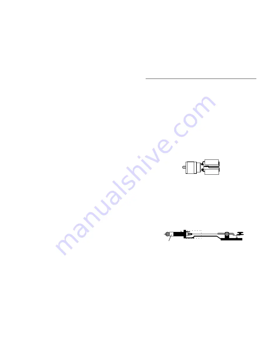
1. 50-ohm dummy load:
A dummy load, or any 47 to 51 ohm
non-inductive
resistor capable of handling one watt, will provide a satisfactory transmitter
termination for testing. Two (2) 100-ohm 1-watt metal oxide resistors
(RadioShack 271-152) connected in parallel across a standard RF connector
work well.
100 ohm
100 ohm
PL258
2. Power Meter:
If you have access to a sensitive power meter, this will
confirm the actual output power of your transmitter. If you don't have a
wattmeter, a standard 5mm LED will provide a rough indication of RF
output (see instructions).
3. Telegraph Key:
The transmitter's keying circuit works with manual keys or
electronic keyers. To plug in, you'll need a standard 1/4" monaural plug.
Ground (or common) is connected to the plug's outer sleeve, and the key line
is connected to the plug's tip.
3.5 mm Phone Plug
Tip
Sleeve
Ring (not used)
Key


