


PI Thermostat TEF
V1.3a, 20100504
© Vector Controls GmbH, Switzerland
Page 5/8
Subject to alteration
Control Function
Temperature Control Mode: PI Control E2=0
The controller reads the temperature either by using its integrated temperature sensor or by using an external
sensor. The controller maintains the temperature set point by calculating the position of the actuator using a 3-
point modulating signal. The on/off actuator is positioned based on its opening and closing time. The
temperature is controlled using a PI control function. If both P and I parts are enabled, they will be added
together to calculate the output position. Following control parameters decide the function of the PI loop:
•
E3: P-band in °K. The p-band corresponds to the temperature difference of current value to setpoint,
which is required for fully opening the output.
•
E4: A large I part increases the swinging tendency of the control loop. Limiting the integral part may
reduce this tendency. The I-part is disabled if 0 is selected.
•
E5: Tn, Reset time of Analog loop integral. Tn is the time needed for the integral to run from 0 to 100%.
The range is 0.5 - 30 min. The setting very much depends on the application it is used for. For
temperature control of a medium sized room, a setting of 5 minutes should be appropriate.
•
P5: Dead Zone Span. The cooling setpoint W
C
consists of the heating setpoint and the dead zone span.
Changing the cooling setpoint therefore changes as well the heating setpoint. The factory setting for the
dead zone span is 1K.
T Room
Temperature
w
H
Setpoint Heating
Xp
E3: Proportional Band
w
C
Setpoint Cooling
Y
T
Output signal of temperature loop
X
DZ
P5: Dead Zone Span
Tn
E5: Integral Reset Time
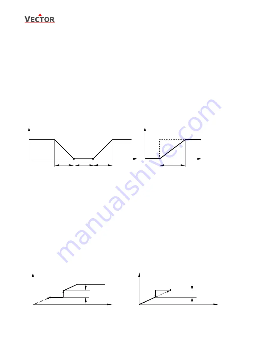
Switching frequency
The TEF works with two digital outputs to modulate a floating actuator. The position of the actuator is calculated
with above described PI algorithm. The controller moves the actuator to the calculated position by either
opening or closing the actuator. The actuator should not be moved for every little change in position, since this
would reduce the lifetime of the actuator. We differentiate if we are moving the actuator in the same direction
as the previous move or if we reverse direction.
•
E7: Switching difference: For example the last actuator movement was opening and we open again. The
actuator will only move, if the difference to the current actuator position is larger than this parameter.
•
E6: Reversing difference: For example the last actuator movement was opening and we want to close
now. The actuator will only move, if the difference to the current actuator position is larger than this
parameter.
Below are examples of switching and reversing difference after the actuator has been opening on its
previous move.
X
T
Calculated actuator position
RD E6: Reversing Difference
Y
T
Actual actuator position
1
Opening up to step 1
SD
E7: Switching Difference
2
Actuator acting point
Y
T
[%]
100
0
SD
Switching Difference
X
T
[%]
Y
T
[%]
100
0
RD
Reversing Difference
X
T
[%]
1
2
2
1
Y
T
[%]
100
0
Xp
W
H
Xp
W
C
Heating Mode P Control Part Cooling Mode
T [°C]
Y
T
[%]
100
0
Tn
W
H/C
I Control Part
t [min]
X
DZ