
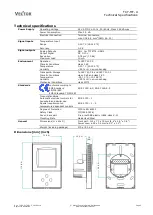


TCY-MT-U
Operation Instructions
Doc: 70-00-0176 V1.2, 20160114
© Vector Controls GmbH, Switzerland
Page 5
Subject to alteration
www.vectorcontrols.com
Configuration parameters for firmware version 1.2
The TCY-MT-U is preset to work for most applications. For special requirements it can be fine-tuned to work ideally with a
simple parameter setup routine. The parameters can be changed on the unit without the need of additional equipment.
Identifying the firmware version
The parameters and functionality of controller depend on its firmware version and revision. It is therefore important to use
a matching product version and parameter set. The Firmware version and revision version can be found when pressing
simultaneously the
and
keys during several seconds. On the upper 7 segment display, the firmware version can be
found, on the lower 7 segment display the current revision index (or “sub-version”).
Access to parameters
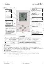
The TCY-MT-U is an
intelligent
controller and can be adapted to fit perfectly into your application. The control operation is
defined by parameters. The parameters are set during operation by using the standard operation terminal.
The parameters are password protected. There are two levels of parameters: User operation parameters for access control
settings and Expert parameters for control functions and unit setup. The passwords for user levels and expert levels are
different. Only control experts should be given the control parameter password.
The parameters can be changed as follows:
1.
Press UP and DOWN button simultaneously for three seconds. The display will indicate the firmware version in the
upper large digits and the revision in the lower small digits. Pressing any key will show: CODE.
2.
Select a password using UP or DOWN buttons. Select 009 in order to get access to the user parameters, 241 for
controls parameters.
Press OPTION after selecting the correct password.
3.
Once logged in, the parameter is displayed immediately
4.
Select the parameters with the UP/DOWN keys. Change a parameter by pressing the OPTION key. The MIN and
MAX symbols show up and indicate that the parameter may be modified now. Use UP and DOWN key to adjust
the value.
5.
After you are done, press OPTION or POWER in order to return to the parameter selection level.
6.
Press the POWER key again so as to leave the menu. The unit will return to normal operation if no key is pressed
for more than 5 minutes.
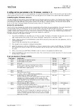
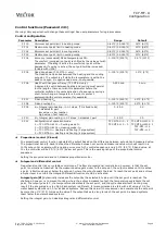
User parameters (Password 009)
Parameter
Description
Range
Default
UP 00
Enable access to operation modes
ON, OFF
ON
UP 01
Enable access to set points
ON, OFF
ON
UP 02
Not used
ON, OFF
OFF
UP 03
Enable manual change of Heating/Cooling Mode.
No influence on TCY-MT2-U-W01(cooling only)or
TCY-MT2-U-W02 (heating only)
ON, OFF
TCY-MT2-W01: OFF
TCY-MT2-W02: OFF
TCY-MT2: ON
TCY-MT4: ON
UP 04
Not used
ON, OFF
OFF
UP 05
State after power failure:
0 = off, 1 = on, 2 = state before power failure
0, 1, 2
2
UP 06
Enable Economy (unoccupied) Mode.
Shift the set point to a lower temperature in winter or higher
temperature in summer in order to save energy. May be
activated through the POWER button, or with the external
input (typically for key card switches in hotel rooms or motion
detectors for meeting rooms.)
ON, OFF
ON
UP 07
ON = Fahrenheit, OFF = Celsius
ON, OFF
OFF (Celsius)
UP 08
Calibrate internal temperature sensor
–10° to +10° in 0.1° steps. (Sensor is factory calibrated, use
this feature for field adjustment only as required.)
-10…10
0.0
UP 09
Enable Frost Protection.
Activates the output independent of operation mode when the
control temperature drops below 5°C or 41°F. The controller
returns to normal operation when the temperature increases
above 10°C or 50°F.
ON, OFF
TCY-MT2-W01: OFF
TCY-MT2-W02: ON
TCY-MT2:
ON
TCY-MT4:
ON


