background image

9

Remove and put on the grip rings
via the head of the seatpost.

Fit the new o-rings into
the groove

2.3

2.4

Summary of Contents for NIVO 122

Page 1: ...Betriebsanleitung S 29 User manual p 2 EN DE ...

Page 2: ... com en products nivo servicefaq There will always be the latest version of the manual online For aquick andeasy installationyou willalso finda videotutorial onthis website Intended use The NIVO dropper post is designed for mountain bikes and their purposes The installation on a road bike is also permitted The NIVO dropper post can handle a max rider weight of 120 kg Installation dimensions You ca...

Page 3: ... 3 Install cable housing 4 Bowden cable installation replacement and adjustment 5 Feature options a TRAVEL FIT b INDEXED 6 Saddle installation 7 Easy maintenance and care 8 Trouble shooting and maintenance 9 Guarantee and Warranty universal pliers 5mm Torx T25 ...

Page 4: ...rt period of getting familiar you will shift your NIVO dropper post intuitively to the individual height positions Please exercise the handling on an easy trail NIVO INDEXED 4 different height positions enabling a fast and repeatable height adjustment NIVO TRAVEL FIT infinte height adjustment and the possibility to set an individual max position Don t lower your dropper post completely when using ...

Page 5: ...en a conventional seat clamp and tooLOC seat clamp conventional seat clamp uneven force distribution into the seat tube This can lead to function restrictions for dropper posts more even force distribution into the seat tube for a perfect dropper post function Forces working load Forces working load Clamping Forces ...

Page 6: ...6 1 Installation preparation Measure most recent maximum Remove old seatpost 1 1 1 2 Make sure to measure the distance between the end of the seat tube and the center of the rail clamp ...

Page 7: ...7 Install tooLOC clamp Extend NIVO 1 3 1 3 Torx T25 ...

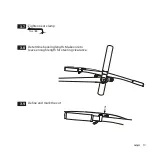
Page 8: ... Remove the recent grip rings A Seatpost not installed Remove and put on the grip rings via the lower end of the seatpost Continue with point 2 4 B Seatpost already installed Remove upper and lower rocker of the rail clamp 2 1 2 2 ...

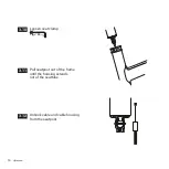
Page 9: ...9 Remove and put on the grip rings via the head of the seatpost Fit the new o rings into the groove 2 3 2 4 ...

Page 10: ...10 Install remote Push cable housing through the frame Make sure the housing extends out of the seattube 3 1 3 2 3 Install cable housing ...

Page 11: ...11 Install end cap 3 3 Install cable in seatpost Make sure the cable head is fixed by the o ring 3 4 ...

Page 12: ...pull the cable to insert the post Install the cable into the housing and plug end cap in the slot 3 5 Insert seatpost into the frame and set it to your desired seat height 3 6 Make sure the seatpost does not collide with any kink or rocker mounts of the frame ...

Page 13: ...13 Tighten seat clamp Torx T25 3 7 Determine housing length Make sure to leave enough length for steering clearance 3 8 Define and mark the cut 3 9 ...

Page 14: ...14 Loosen seat clamp Torx T25 3 10 Pull seatpost out of the frame until the housing extends out of the seattube 3 11 Unhook cable and cable housing from the seatpost 3 12 ...

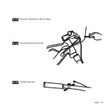
Page 15: ...15 Remove cable from the housing 3 13 Cut housing at the mark 3 14 Install end cap 3 15 ...

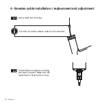
Page 16: ...e cable to make it run smoother Insert cable into housing 4 1 Install cable in seatpost and plug end cap in the slot Make sure the cable head is fixed by the o ring 4 2 4 Bowden cable installation replacement and adjustment ...

Page 17: ...ote Make sure the cable has no play 4 5 For inserting the post always push the seatpost Do not pull the cable to insert the post Make sure the seatpost does not collide with any kink or rocker mounts of the frame Before cutting the cable check the function 1 NIVO does not lock properly Reduce cable tension 2 Remote has free travel Increase cable tension ...

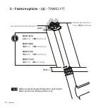
Page 18: ...k position with tape at the seal 5 1 5 Feature options a TRAVEL FIT Maximum position max 212mm travel Desired maximum position 19 5mm 22 5mm NIVO 212 212mm 180mm travel NIVO 182 182mm 150mm travel NIVO 152 152mm 120mm travel NIVO 122 122mm 90mm travel ...

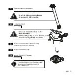
Page 19: ...e red rubber cap 5 5 To set the right position make sure the seatpost is fully extended Make sure to clean the head of the NIVO thoroughly Dust and dirt getting inside of the seat post can cause damage to the mechanics Unlock TRAVEL FIT feature 5 6 5mm Turn the allen key only for one klick No strength needed to unlock or lock TRAVEL FIT ...

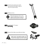
Page 20: ...ravel by pushing the seatpost down to the tape marker 5 7 5 10 Lock TRAVEL FIT feature 5 9 5mm Release remote 5 8 After releasing the remote move seatpost a little bit up an down to make sure the position is locked Make sure to reinstall the rubber cap Head of the seatpost must be closed ...

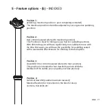
Page 21: ...ificantly more ability to move with the bike Moreover you will have the possibility for pedalling seated with a reasonable effectiveness for climbing technical uphills Position 3 Downhill 100 or 90 mm lowered referred to max position This position is intended for fast downhill sections With the feedback of the saddle you can guide your bike precisely Position 4 technical downhill saddle maximum lo...

Page 22: ...d nut from upper rocker of the rail clamp Put the saddle rail into the lower rocker of the rail clamp Put the upper rocker back onto the saddle rail Hang up the rear clamp bolt into the upper rocker 6 2 6 3 6 4 6 5 5mm 6 Saddle installation ...

Page 23: ... 6 Tighten rear bolt to lower the saddle back Tighten front bolt to lower the saddle nose Adjust saddle tilting first then horizontal position 5mm 8 5 8 5 0 32mm Adjust saddle position 5mm 73 default angle ...

Page 24: ...24 Tighten the clamp bolts 6 7 Please check torque of the clamping bolts after first couple of hours used Note maximum torque Shake saddle strongly and check torque of the bolts again 6 8 5mm 6 max 8Nm ...

Page 25: ...mm If you use an extreme tilting or a carbon saddle with high oval shaped rails it may happen that the standard M6x30m Titanium bolts do not reach the 6mm supporting thread In our online shop https shop vecnum com we offer longer bolts M6x35 for this special application min 6mm ...

Page 26: ...ion of the upper sealing unit at least every 3 months If you are running the post in dusty or muddy environment a relubrication after 1 5 month is helpful Before riding you have to check the dropper post for damages We recommend grease with low viscosity for lubrication of the upper sealing unit Our advice Dynamic Hochleistungsfett available in many German bike online stores ...

Page 27: ...27 Put some grease onto the upper post tube Our recommendation grease with low viscosity 7 4 Slide back the seal housing and tighten it by hand Clean the upper post tube from surplus grease 7 5 7 6 ...

Page 28: ...bH grants a warranty of two years as required by law Wear by using the products is not covered by warranty As all moving parts on the bike also the NIVO dropper post needs the recommended maintenance and will show wear The service intervals durability depends on operating conditions Sealings bushings and glide surfaces are subject to wear Furthermore the guarantee does not cover damages caused by ...

Page 29: ...produkte nivo servicefaq immer die neueste Version der Bedienungsanleitung zum Download Um den Einbau der Sattelstütze weiter zu vereinfachen haben wir dort auch ein Video hinterlegt Darin lassen sich alle notwendigen Arbeitsschritte genau nachvollziehen Bestimmungsgemäßer Gebrauch Die NIVO Sattelstütze wurde für Mountainbikes und deren vorgesehenes Einsatzgebiet konstruiert Ein Einsatz der NIVO S...

Page 30: ...ringe tauschen 3 Zughülle montieren 4 Zug montieren tauschen und spannen 5 Featureoptionen a TRAVEL FIT b INDEXED 6 Sattel montieren 7 EinfachePflege und Wartung 8 Problembehebung und Service 9 Garantie und Gewährleistung Combizange 5mm Torx T25 ...

Page 31: ...führen und dadurch einen Sturz mit schwerwiegenden Folgen verursachen NIVO INDEXED 4 verschiedene Höhenpositionen ermöglichen eine schnelle und exakt wiederholbare Höhenverstellung NIVO TRAVEL FIT stufenlos verstellbar Eine individuelle Maximalposition kann definiert und eingestellt werden Bei Liftbetrieb mit Schleppliften Sattelstütze bitte nicht komplett versenken da durch den Lifthaken der Dich...

Page 32: ...h Krafteinwirkungen herkömmliche Sattelstütze und tooLOC herkömmliche Sattelklemme ungleichmäßigeKrafteinwirkungaufdas FührungsrohrderStütze DieskannzuFunktionseinschränkungender versenkbarenSattelstützeführen gleichmäßigeKrafteinwirkungaufdas FührungsrohrderStütze KräfteBetriebsbelastung KräfteBetriebsbelastung Klemmkräfte ...

Page 33: ...33 1 Montagevorbereitung Sitzhöhe ausmessen Alte Sattelstütze ausbauen 1 1 1 2 Strecke zwischen Ende Sitzrohr und und Mitte des Sattelgestells messen ...

Page 34: ...34 tooLOC Klemme montieren NIVO vollständig ausfahren 1 3 1 3 Torx T25 ...

Page 35: ...en Vorinstallierte Ringe aus den Nuten rollen A Sattelstütze nicht eingebaut Ringe nach unten abnehmen und wieder auffädeln Weiter mit 2 4 B Sattelstütze bereits eingebaut Beweglicher Teil des Stützenkopfs lösen und abnehmen 2 1 2 2 ...

Page 36: ...36 Ringe über den Stützenkopf abnehmen und auffädeln Ringe in die Nuten rollen 2 3 2 4 ...

Page 37: ...37 Daumenfernbedienung montieren Zughülle durch den Rahmen fädeln Auf ausreichend Überstand am Sitzrohr achten 3 1 3 2 3 Zughülle montieren ...

Page 38: ...38 Endkappe montieren 3 3 Bowdenzug in Sattelstütze einhängen Zugkopf muss vom O Ring im Schlitten gesichert sein 3 4 ...

Page 39: ... das der Zug und die Hülle in der dafür vorgesehener Halterung montiert sind Zug in Hülle einfädeln und die Zughülle mit der Endkappe in die Stütze stecken 3 5 Sattelstütze auf die gewünschte Sitzhöhe in den Rahmen schieben 3 6 Beim Einschieben sicherstellen dass die Stütze nicht im Rahmen anstößt ...

Page 40: ...40 Sattelklemme anziehen Torx T25 3 7 Länge der Zughülle festlegen Lenkeinschlag beachten 3 8 Schnitt markieren 3 9 ...

Page 41: ...41 Sattelklemme lösen Torx T25 3 10 Sattelstütze wieder aus dem Rahmen ziehen bis die Hülle am Sitzrohr übersteht 3 11 Zug und Zughülle aus der Sattel stütze aushängen 3 12 ...

Page 42: ...42 Zug aus Zughülle herausziehen 3 13 Zughülle an der markierten Stelle kürzen 3 14 Endkappe montieren 3 15 ...

Page 43: ...ür eine geschmeidige Bedienung dünnes Öl auf den Zug geben Zug in Zughülle fädeln 4 1 Zug in Hülle einfädeln und die Zughülle mit der Endkappe in die Stütze stecken 4 2 4 Zug montieren tauschen und spannen ...

Page 44: ...el haben 4 5 Beim Einschieben sicherstellen dass die Stütze nicht im Rahmen anstößt Vor dem Zug kürzen Funktionstest machen 1 NIVO verriegelt nicht Zugspannung reduzieren 2 Daumenfernbedienung hat Leerweg Zugspannung erhöhen Sattelstütze in den Rahmen schieben Nicht mit dem Bowdenzug ziehen Es muss sichergestellt sein das der Zug und die Hülle in der dafür vorgesehener Halterung montiert sind ...

Page 45: ...erhalb der Dichtung am Rohr markieren 5 1 5 Featureoptionen a TRAVEL FIT Maximalposition max 212mm travel Gewünschte Maximalposition 19 5mm NIVO 212 212mm 180mm travel NIVO 182 182mm 150mm travel NIVO 152 152mm 120mm travel NIVO 122 122mm 90mm travel 22 5mm ...

Page 46: ...ote Gummikappe abnehmen 5 5 Um die richtige Position einstellen zu können muss die Sattelstütze maximal ausgefahren sein Stützenkopf gründlich säubern Staub und Schmutz dürfen nicht ins Innere gelangen Die Mechanik kann dadurch Schaden nehmen TRAVEL FIT öffnen 5 6 5mm Inbusschlüssel lediglich einen Klick drehen Es braucht keine Kraft um TRAVEL FIT zu öffnen schließen ...

Page 47: ...d Sattelstüze zur Klebemarkierung herunterdrücken 5 7 5 10 TRAVEL FIT schließen 5 9 5mm Daumenfernbedieung loslassen 5 8 Nach dem Loslassen der Daumenfernbedienung die Stütze etwas hoch und runter bewegen damit die Mechanik einrastet Die rote Gummikappe muss gut sitzen Der Stützenkopf muss geschlossen sein ...

Page 48: ...ie Absenkung von 40mm bietet bereits deutlich mehr Bewegungsfreiheit bei gemäßigten Bergab Passagen Zugleich kann in dieser Sattelposition auch im Sattel sitzend relativ effizient pedaliert werden um so technische Anstiege etc zu überwinden Position 3 Downhill 100 bzw 90mm abgesenkt zur Maximal Position Diese Position eignet sich für schnelle Downhill Passagen Das Bike kann mit den Beinen optimal ...

Page 49: ...glichen Teil des Stützenkopfs nehmen Sattel mit dem Gestell in die Sattelauflagerillen legen Beweglichen Teil des Stützenkopfs auf das Sattelgestell legen Schraube und Mutter in den beweglichen Teil des Stützenkopfs einlegen 6 2 6 3 6 4 6 5 5mm 6 Sattel montieren ...

Page 50: ...ntere Schraube anziehen Sattelende senken Vordere Schraube anziehen Sattelpitze senken Zuerst Sattelneigung einstellen dann horizontale Position 5mm 8 5 8 5 0 32mm Sattelposition einstellen 5mm 73 Ausgangswinkel ...

Page 51: ...n abwechselnd Schritt für Schritt anziehen 6 7 Klemmschrauben nach ca 1 2 Stunden Fahrtzeit nachziehen Drehmoment beachten Kräftig am Sattel rütteln und bei Bedarf die Schrauben nochmal etwas anziehen 6 8 5mm 6 max 8Nm ...

Page 52: ... Sattel optimal befestigt zu haben Bei extremen Neigungswinkeln oder bei hochovalen Sattelgestellen kann es vorkommen dass mit der mitglieferten M6x30 Klemmschraube die 6mm nicht eingehalten werden können In unserem Shop auf https shop vecnum com gibt es M6x35 Schrauben zum Nachrüsten min 6mm ...

Page 53: ...testens nach 3 Monaten Betrieb die Dichtung zu schmieren Bei staubigen oder matschigen Bedingungen sollte das Schmieren schon nach 1 5 Monaten erfolgen Vor jeder Fahrt Sattelstütze auf äußere Schäden und funktionale Einschränkung kontrollieren Wir empfehlen für die Schmierung der oberen Dichteinheit ein dünnflüssiges Fett Unsere Empfehlung Dynamic Hochleistungsfett im Fachhandel erhältlich ...

Page 54: ...was Fett auf das obere Stützenrohr auftragen Unsere Empfehlung Dynamic Hochleistungsfett 7 4 Dichtungsmutter zurück schieben und von Hand anziehen Überschüssiges Fett vom oberen Stützenrohr abwischen 7 5 7 6 ...

Page 55: ...ährige Gewährleistung Verschleiß durch normalen Gebrauch unterliegt nicht der Garantie Wie alle beweglichen Teile am Bike erfordert auch die NIVO Sattelstütze entsprechende Wartung und unterliegt Verschleiß Die Wartungsintervalle Lebensdauer der Verschleißteile sind von der Häufigkeit des Gebrauchs bzw von den Einsatzbedienungen abhängig Dichtungen Gleitlager Verschleiß an Gleitflächen sind ein no...

Page 56: ...56 Vecnum GmbH Am Angele Hof 33 88316 Isny im Allgäu Deutschland Kommunikation Telefon 49 0 7562 9743775 info vecnum com www vecnum com 09 2020 ...

Reviews: