


Taking safety precautions, Fig. 1
A
Before starting work, disconnect the earth cable from the vehicle battery’s negative terminal
in order to prevent short circuits. For this purpose, follow the vehicle manufacturer’s safety
instructions (alarm system, airbag, immobiliser, etc.).
Electrical connections, Fig. 2
☞
Route all cables with care. For the cabling, refer to the connection illustration on the
cover pages and the following table.
☞
Do not cut off non-assigned cables. Instead, wrap them up and fix them to one side. They
may be necessary for retrofitting additional functions.
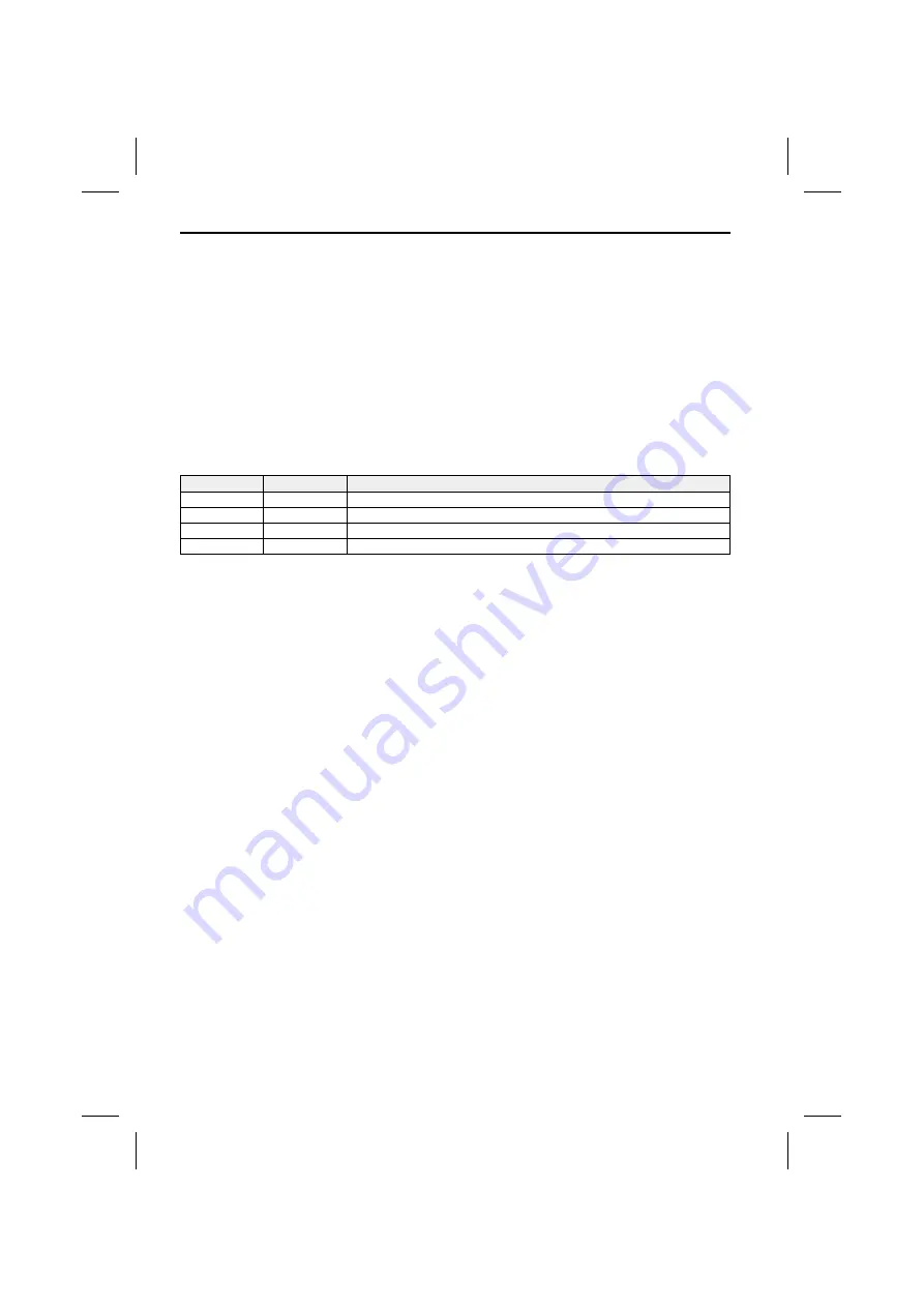
Power supply connection
Cable colour
Category
Connection
Yellow
Input
+ 12 V permanent positive (must be rated for a current of at least 3 amps)
Red
Input
+ 12 V ignition positive (switched plus)
Black
Input
Battery negative (vehicle chassis)
Blue/white
Output
12 V Remote out (max. output current: 0.5 amps)
A
Only connect electrical signals to suitable connecting points in the vehicle.
A
If connection is made directly to the battery, protect the positive lead (red lead) with a 10 A
fuse close to the battery (max. distance 10 to 15 cm).
■
12 V permanent positive (yellow):
☞
Connect yellow lead to a suitable connector with 12 V permanent positive.
A
This connection should be rated for a current of at least 3 amps.
■
12 V ignition positive (red):
☞
Connect red lead to a suitable 12 V circuit switched through the ignition.
■
12 V Remote out (blue/white):
☞
Connect blue/white lead to the remote input of accessory units (for example a multimedia
interface box).
■
Battery negative (black)
☞
Connect black lead to a suitable ground (vehicle chassis).
AV out connection
☞
Connect the yellow “VIDEO” plug to the Video input of your multimedia system.
☞
Connect the “AUDIO-L” (white) and the “AUDIO-R” (red) lead to the left and right line or
AUX input of your multimedia system.
☞
If applicable, connect the optical SPDIF output to the appropriate input of your
multimedia system.
Remote control receiver
☞
Connect the remote control receiver connector to the “IR” socket at the fly-lead on the
back of the unit.
INSTALLATION INSTRUCTIONS
10
Summary of Contents for DV 6100
Page 3: ...3 1 2 3...


