

User manual
Document no. : 032189
Version : V1.5
MC 785 CHILLER-2
Customer: Heinen & Hopman
Page: 9 of 16
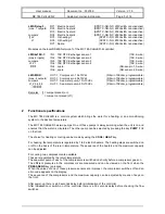
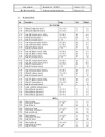
No.
Description
Range
Unit
Default
P120
P121
P122
Minimum adjustable temperature setpoint heater
Maximum adjustable temperature setpoint heater
Heaters present
0.0..+90.0
0.0..+90.0
0 = no, 1 = yes
O
C
O
C
-
+30.0
+40.0
1
Cooling
P200
P201
Start delay compressors if the regulator has been out
for more than P201 hours.
Regulator out - hours limit
0...100
0...100
hour
hour
8
4
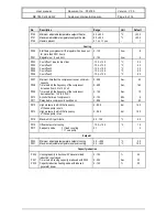
P202
P203
P204
P205
P206
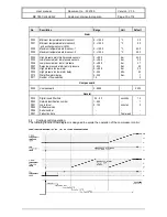
Cool offset-1 (see function flow)
Cool offset-2
Cool offset-3
Cool offset-4
Cool offset-5
-10.0...+10.0
-10.0...+10.0
-10.0...+10.0
-10.0...+10.0
-10.0...+10.0
°C
°C
°C
°C
°C
0.0
0.0
3.0
3.0
6.0
P207
P208
P209
P210
P211
Minimum time that the compressor runs at minimum
capacity
Time in which the frequency of the compressor
increases from 0,0 to 10,0 Volt
Time in which the frequency of the compressor
decreases from 10,0 to 0,0 Volt
Anti shuttle time of compressors
Delay before compressor-2 switches on
0...999
0...999
0...100
0...100
0...999
Sec.
Sec.
Sec.
Min.
Sec.
60
180
15
5
60
P212
P213
High pressure in which the frequency
of the sea pump is zero.
High pressure in which the frequency
of the sea pump is ten.
0...99.9
0...99.9
bar
bar
14.0
19.0
P214
Maximum chill per minute
0.0...10.0
°C
0.2
P215
P217
Offset set point at cooling
Sea pump mode
0 = fixed coupling
1 = 1 sea pump
-15.0...+15.0
0..1
°C
-
1.5
0
Setpoint
P220
P221
Minimum adjustable temperature setpoint cooling
Maximum adjustable temperature setpoint cooling
0.0...+90.0
0.0...+90.0
°C
°C
5.0
12.0
Capacity reduction
P230
P231
P232
Cooling capacity reduction with “Generator load
reduction” input closed
Time in which cooling capacity is reduced with P230
Capacity reduction heating-mode with reduced
generator power
0...100
5...300
0...100
%
Sec.
%
40
20
50