


VC4XXX_HW.pdf – Hardware Documentation VC4XXX Smart Cameras
1996-2014 Vision Components GmbH Ettlingen, Germany
30
6.2.5
Electrical Specifications of Trigger- / Serial-/ Keypad / Encoder Interface
The trigger interface features a dedicated fast TTL trigger input (for use as image capture trigger) and
a fast TTL trigger output (as strobe-light trigger). Since both signals are fast at a very low noise
margin, it is recommended to keep the cable as short as possible. Use shielded cable for this purpose.
Neither the trigger input nor the trigger output has
an inbuilt-in photo coupler
2
. Please ensure
that the electrical specifications of this section are met and provide galvanic isolation to trigger
input and output if necessary.
Please note that input and output are not protected against over current. The output is neither
protected against short circuit nor reverse voltage spikes from inductive loads.
The trigger input assures constant delay without jitter.
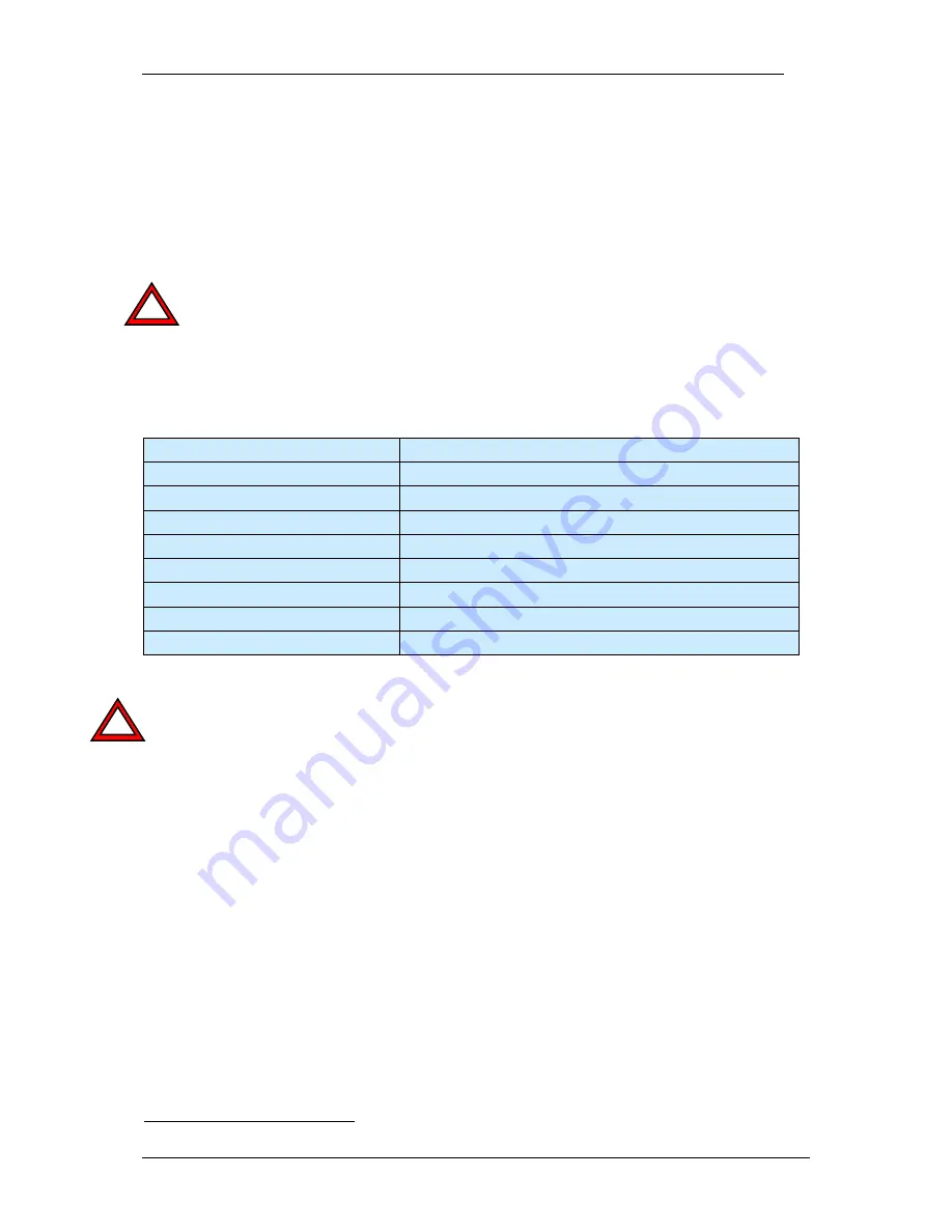
Technical data of trigger input:
input voltage:
2.4 - 5 V (TTL, CMOS)
input current:
3mA @ 3V / 5mA @ 5V
limiting resistor:
none
pull down resistor 1 k
Ω
Included in later models
Opto- isolation:
none
reverse voltage protection:
none
switching delay:
Max. 2µsec + interrupt latency
Capture delay
Approx 40µsec (constant), for jitter free operation
Max encoder signal frequency
25 MHz
Note the modified circuit of the trigger input, due to the additional RS232 interface. Old trigger input
circuits need to be modified in order to prevent damaging the trigger input of the VC40XX camera. See
the introduction of section 6.2 for details. The use of a transistor in the trigger input circuit is
recommended as shown in the following figures. These are sample circuits only – please check the
final circuit layout as this depends largely on the sensor / equipment connected.
Please also note that the GND of the Trigger/ RS232 interface is not identical with the Power Supply/
PLC GND, GND IN com. (refer to section 6.3).
Selection of a suitable TTL encoder for direct connection to the trigger interface
A suitable TTL encoder can be connected directly to the encoder interface. The encoder power supply
can be done using the 5V and GND outputs of the trigger interface. The 0+, A+, B+ encoder signals
can be connected according to section 6.2.1 An encoder with “push- pull” output characteristic can
save a pull down resistor on the trigger input (refer to “Encoder.pdf” – see References on page 2).
Do not exceed the current rating of
50 mA
for the 5V out, pin 2 (keypad, encoder power supply).
The input voltage of the trigger input needs to be at least 2.4V (maximum Voltage: 5V).
Tested incremental encoder:
-
2420 range of miniature encoders, TTL, Ub = 5-24V, Signal Level = Ub -2.5V, push pull,
manufacturer: Kübler GmbH,
www.kuebler.com
-
Siemens 1XP8001-2, TTL, Ub = 5-10V, for 3 phase 220V asynchrone motor, size H58 Din 332
2
The VC Base Family camera range VC4018 and -16 incorporate opto coupler on trigger in and out.
!
!


