6
(Note: Sensor does NOT need to make intimate contact with
entire well surface to work properly)
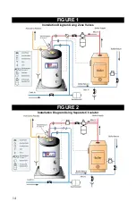
The TOP PERFORMER may operate as a separate heating zone
using either the heating system circulator and an appropriate
zone valve, or a separate circulator dedicated for water heating.
(See Figure 1 & 2).
(See Figure 3 for S70DTPP)
In both systems, the TOP PERFORMER is controlled through the
thermostat on the heater.
(See Figures 1 & 2).
(See Figure 3 for
S70DTPP)
Be certain to replace thermostat cover using Black Screw
provided.
J. ETC101 WIRING CONTROLS
WARNING:
Do not use ETC101 with 110V circuits. For Switching
110V, use a standard TPI Control.
For controlling zone valves, multi-zone controllers and switching
relays, follow applicable wiring diagrams for typical low voltage
thermostat circuits.
Some newer switching relay models do not work properly with
“Power Stealing” thermostats. The ETC101 is a power stealing
thermostat unless powered separately. Connect 24VAC Power
(From the the switching relay board or from a step down
transformer to the screws to the right of the Probe Connector.
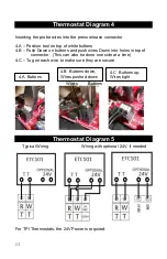
(See Thermostat Diagram 5)
K. TPI WIRING CONTROLS
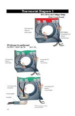
NOTE: THE TPI THERMOSTAT MUST BE POWERED WITH 24V
AC
24V
AC
power must be connected to 24V
AC
connectors on the
bottom right corner of TPI. (See THERMOSTAT Diagram 3)
The TPI 24V
AC
only requires 20mA, or about 0.5 Watts.
Connect control wiring to PUMP/TT normally open relay
connections (rated for both 24V and 110V wiring) on the bottom
left corner of TPI.
(See Thermostat Diagrams 3 and 5)
All and only 110V
AC
wiring must go through an appropriate chase
nipple installed in the knockout at bottom of TPI case.
TPI Wiring will vary depending on the type of boiler and valve
controls in the system. Consult attached Wiring Diagrams for
appropriate wiring configuration for your system.
CAUTION: If Sensor is soldered directly to TPI, DO NOT BEND
SHARPLY OR OVERWORK.
L. INSULATION INSTALLATION
Place included fiberglass insulation between and around the
water supply and boiler supply connections. Attach lid using
screws provided. Insulate hot water pipes with pipe insulation.
Summary of Contents for TOP PERFORMER PLUS
Page 14: ...11 Thermostat Diagram 1 Thermostat Diagram 2...
Page 19: ...16 FIGURE 4...


