


USER MANUAL
Vauconsant SA, all rights reserved A625xx -rev0-ENG, 14/10/2010 - 7 -
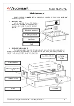
Cleaning
Always take care to switch off the appliance with energy doser, thermostat and switch before
cleaning. This unit is not impermeable to water. Do not use a high pressure water jet to clean it
inside or out.
Every day:
•
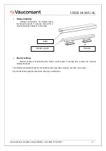
Metal surfaces:
Stainless steel should be cleaned with soapy warm water or a special product for high quality
metal surfaces. Never use abrasive sponges or etching agents to avoid scratching the surface.
•
glass (breath shield):
All glass displays must be cleaned using a high quality glass cleaning product and clean cloth.
Never use abrasive sponges or etching agents to avoid scratching the surface.
Diagnostic
Symptoms
Possible causes
Remedies
No electricity supply
Check the general circuit breaker
Burnt fuse
Check the fuse in the electric cabling
Light off, no
heat
Faulty supply
Check the supply cable
Cable disconnected or cut
Check and test the electric input on the heating elements
Light on, no
heat
Defective heating element
Replace the heating element
Burnt fuse
Check and replace fuse 2A
Defective ventilator
Test and replace the ventilator
B
a
in
-m
a
ri
e
w
e
ll
No ventilation
Faulty supply
Check the ventilator's supply cable
No electricity supply
Check the general circuit breaker
Burnt fuse
Check the fuse in the electric cabling
Light off, no
heating or
ventilation
Faulty supply
Check the supply cable
Defective heating element
Replace the heating element if necessary
Cable disconnected or cut
Check and test the electric input on the heating elements
Light on, no
heat
Defective safety thermostat
Check and test the electric inlet on the safety thermostat.
Ventilator blocked or
defective
Clean or replace the ventilator
V
e
n
ti
la
te
d
h
e
a
t
c
u
b
o
a
rd
Light on, no
ventilation
Cable disconnected or cut
Check and test the electric input on the ventilator
Halogen bulb burnt
Replace the bulb with one of equivalent power
A halogen
lamp does not
come on
Supply of this defective
halogen
Check supply of halogen
No electricity supply
Check the general circuit breaker
Burnt fuse
Check the fuse in the electric cabling
Faulty supply
Check the supply cable to the heating display
H
a
lo
g
e
n
l
ig
h
ti
n
g
:
None of the
halogen lights
come on
Defective switch
Check the switch, replace it if necessary
NB
•
Bulbs should be replaced with bulbs of equivalent power. (see the Spare Parts section)
•
Fuses should be replaced by gG fuses of the same caliber.