background image

MAINTENANCE 

Series 65


86/110 

Edition 2019-06-05 

982156EB


7.2 

Maintenance procedures 

Two maintenance procedures are defined for this valve. These are: 


Replacement of isolation seals (gate and body seal of sealing ring) and valve cleaning  


Replacement of actuator shaft seals 


Required frequency of cleaning and replacement of seals is depending on process 
conditions. 

VAT can give the following recommendations for preventive maintenance: 
 

Replacement of 

unheated 

1)


heated 

 80 °C 

1)


heated > 80 °C 

1)


isolation seals (gate and 
body seal of sealing ring) 

12 month but max. 
200’000 cycles 

6 months but 
max. 200’000 cycles 

3 months but 
max. 200’000 cycles 

actuator shaft seals 

1’000’000 cycles 

6 months 

3 months 


1)

 Those figures are reference values for clean conditions under various temperatures. 

These values do not include any impact of the process. Therefore preventive 
maintenance schedule has finally to be checked for the actual process conditions. 


NOTICE 

Vacuum grease 

Vacuum grease may be distributed and contaminate the valve. 

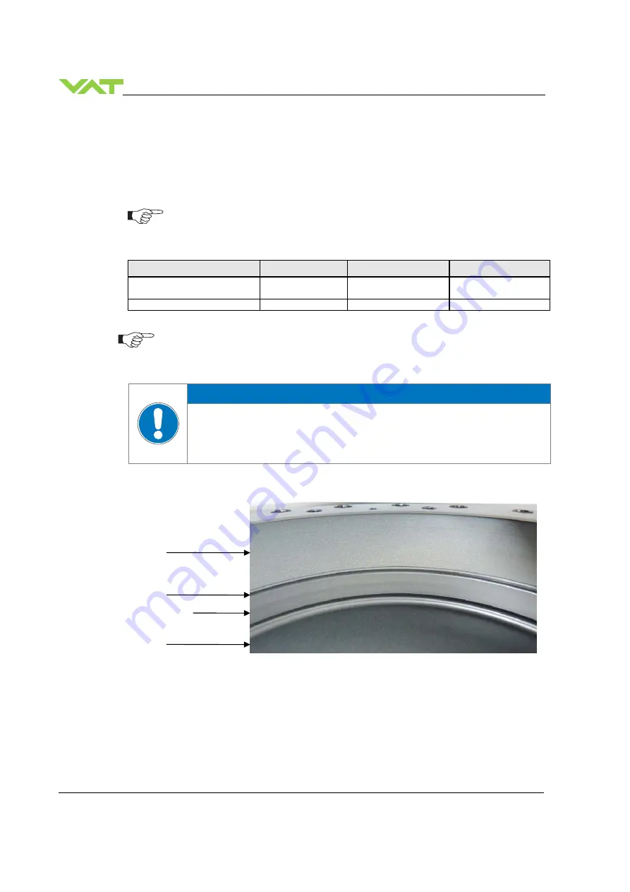
Prevent gap between body and sealing ring from air gun cleaning. Do not clean the 
gap between body and sealing ring with compressed air. 

 
See figure below: 


Body 


Gap 


Sealing ring 
 
 
Plate 

Summary of Contents for 653 AQ Series

Page 1: ...d for the valve ordering number s 653 GQ 2 sensor inputs analog outputs 653 AQ 2 sensor inputs analog outputs 15V SPS 653 HQ 2 sensor inputs analog outputs PFO 653 CQ 2 sensor inputs analog outputs 15...

Page 2: ...duplicated or distributed without written permission from VAT Offenders are liable to pay damages The original VAT firmware and updated state of the art versions of the VAT firmware are intended for u...

Page 3: ...ng with O ring in grooves 24 4 2 7 Admissible forces 25 4 2 8 Requirements to sensor connection 26 4 3 Electrical connection 26 4 3 1 Ground connection 27 4 3 2 Power and sensor supply concepts 28 Ext...

Page 4: ...5 1 Normal operation 76 5 1 1 Remote operation 76 5 1 2 Local operation 77 5 2 Close valve 78 5 3 Open valve 78 5 4 Position control 78 5 5 Pressure control 78 5 6 Display information 79 5 6 1 Power u...

Page 5: ...Edition 2019 06 05 5 110 10 2 Transport 103 11 Disposal 104 12 Spare parts 105 12 1 Drawing 105 12 1 1 Valve unit with seals and grease 106 12 1 2 Control and actuating unit 107 12 1 3 Accessories 10...

Page 6: ...se product for clean and dry vacuum applications only Other applications are only allowed with the written permission of VAT 1 3 Used abbreviations Abbreviation Description CPA Control Performance Ana...

Page 7: ...VDC 5 1200 mA max connector POWER connector SENSOR Sensor power supply 2 653 G 653 H input output 24 VDC resp 15 VDC same as input but 2 0 A max at 15 VDC 1 5 A max at 24 VDC connector POWER connecto...

Page 8: ...d valve closed adjustable with CPA valve opened adjustable with CPA connector POWER max 70 V 0 1 A connector POWER Digital inputs 4 voltage control contact control 5 24V 2 10 mA 3 3V 2 mA connector IN...

Page 9: ...typ 0 45 s typ 0 9 s typ 0 5 s typ 0 9 s typ 0 5 s typ Opening time throttling only full stroke 0 7 s typ 0 4 s typ 0 8 s typ 0 45 s typ 0 9 s typ 0 5 s typ 0 9 s typ 0 5 s typ Closing time throttlin...

Page 10: ...0 000 unheated and under clean conditions 1 000 000 unheated and under clean conditions Admissible operating temperature 10 C to 120 C Mounting position horizontally only Wetted materials Body 653 A A...

Page 11: ...00 mbar in either direction 1200 mbar in either direction 1200 mbar in either direction 1200 mbar in either direction Max differential pressure on plate during opening and throttling 30 mbar 10 mbar 5...

Page 12: ...ion Operating Maintenance Instructions are an integral part of a comprehensive documentation belonging to a complete technical system They must be stored together with the other documentation and acce...

Page 13: ...ions WARNING Unqualified personnel Inappropriate handling may cause serious injury or property damage Only qualified personnel are allowed to carry out the described work 2 4 Safety labels Label Part...

Page 14: ...156EB 3 Design and Function 3 1 Design 1 Plate seal 7 Rotary feed through seals 2 Body seal 8 Pendulum plate 3 Shaft feed through seals 9 Sealing ring 4 Bonnet seal 10 Bonnet 5 Actuator 11 Body 6 Inte...

Page 15: ...stepper motor An encoder monitors the position This principle ensures fast and accurate process pressure control For opening or control the sealing ring is lifted pneumatically by compressed air afte...

Page 16: ...nces Example Downstream control 1 Valve 2 Process chamber 3 Gas inlet 4 Pressure sensor s 5 Sensor cable 6 Controller and actuator 7 Cable to remote control unit 8 Cable to power supply 9 HV Pump Seff...

Page 17: ...into which gas is admitted at the same time the pressure can be controlled in two ways 1 Downstream control standard The pressure is controlled by changing the conductance of a control valve between...

Page 18: ...sical overstraining Use a crane to lift valves DN 200 8 and larger Make sure that the supplied products are in accordance with your order Inspect the quality of the supplied products visually If it do...

Page 19: ...not be touched NOTICE Sealing surfaces Sealing surfaces of valve and vacuum system could be damage in case of incorrect handling Only qualified personal are allowed to install the valve into the vacuu...

Page 20: ...he valve with integrated controller with space for dismantling and air circulation as shown in figure below 4 2 2 Connection overview System 1 Valve 2 Process chamber 3 Gas inlet 4 Pressure sensor s 5...

Page 21: ...Series 65 INSTALLATION 982156EB Edition 2019 06 05 21 110 Controller...

Page 22: ...rect wiring 8 This valve has a double sealed rotary feedthrough and optionally an intermediate pumping port for the actuator shaft This port 1 8 ISO NPT could be connected to the vacuum line see Figur...

Page 23: ...ved surface quality surface treatment and lubrication The torques below are valid if immersion depth of the mounting screws is at least once the thread diameter min 1d and the friction coefficient of...

Page 24: ...bs ft DN100 4 65340 20 23 35 40 35 40 15 17 26 30 26 30 DN160 6 65344 35 40 35 40 35 40 26 30 26 30 26 30 DN200 8 65346 35 40 35 40 80 90 26 30 26 30 59 67 DN250 10 65348 35 41 65 70 80 90 26 30 48 52...

Page 25: ...higher force the valve body as specified The following forces are admissible Valve size Axial tensile or compressive force FA Bending moment M N lb Nm lbf DN100 4 65340 1000 220 40 30 DN160 6 65344 2...

Page 26: ...present Make also sure that there is no obstruction in front of sensor connection port inside the chamber The sensor should also be mounted free of mechanical shock and vibration Dynamic stray magnet...

Page 27: ...ion plates of ground strap must be total plane for a good electrical contact The connection point at chassis FE must be blank metal not coated It is also possible to connect the ground strap at system...

Page 28: ...nsor connection 24 VDC sensors 15 VDC sensors External 15 VDC supplied to POWER connector is feedthrough to SENSOR connector Refer to chapter Power and sensor connection 15 VDC sensors without optiona...

Page 29: ...ay from noise sources Connect Power supply 24 GND at DA 15 male power connector and Sensors 24V 0V at DA 15 female sensor connector exactly as shown in the drawing above Connector Use only screws with...

Page 30: ...ay from noise sources Connect Power supply 24 GND at DA 15 male power connector and Sensors 0V at DA 15 female sensor connector exactly as shown in the drawing above Connector Use only screws with 4 4...

Page 31: ...away from noise sources Connect Power supply 24 GND and GND 15V 15V at DA 15 male power connector and Sensors 15V 15V 0V at DA 15 female sensor connector exactly as shown in the drawing above Connecto...

Page 32: ...ocate it away from noise sources Connect Power supply 24 GND at DA 15 male power connector and Sensors 0V at DA 15 female sensor connector exactly as shown in the drawing above Connector Use only scre...

Page 33: ...ay from noise sources Connect Power supply 24 GND at DA 15 male power connector and Sensors 15V 15V 0V at DA 15 female sensor connector exactly as shown in the drawing above Connector Use only screws...

Page 34: ...and 2 digital outputs Digital inputs may be operated either by switches or by voltage sources Active digital inputs have higher priority than DeviceNet commands Do not connect other pins than indicate...

Page 35: ...itched off The function can be set to function INTERLOCK CLOSE INTERLOCK CLOSE has priority over INTERLOCK OPEN 14 INPUT COMMON Common for all digital inputs See also 4 3 3 4 Digital output Pin Functi...

Page 36: ...CAN_L Blue DeviceNet signal The DeviceNet interface is galvanic isolated from control unit 4 3 4 1 Micro Connector Pinout Male pins at valve controller Female sockets at DeviceNet cable 4 3 5 Service...

Page 37: ...et Baud rate and Address for valve must be selected Refer to chapter Interface configuration DeviceNet for details 4 SENSOR CONFIGURATION Basic configurations of the valve must be adapted according to...

Page 38: ...es when the valve performs the homing procedure Standard Do homing after restart if valve is not in sealed state Open Command Do homing on an open command Move Command Do homing on any move command At...

Page 39: ...y in Pressure Controller Object Class ID 100 4 5 3 Digital I O On the power connecter there are two digital inputs and two digital outputs available See chapter Power and sensor connection to get more...

Page 40: ...n the unit of Range Data Unit Example for a 250mTorr linear sensor Upper Limit 250 0 Lower Limit 0 0 Range Upper Limit Voltage Value Range Lower Limit Voltage Value These parameters are only used for...

Page 41: ...oth sensors need to fit together in the crossover area otherwise crossover effect result nonlinearity Therefore sensor ratio should not be too high about 100 Crossover Mode Hard Switch Switching betwe...

Page 42: ...nsor x Offset Value SFS 0 0 Sensor 1 Enable Sensor 2 Enable 0 It s not possible to execute a zero adjust A present offset value is ignored 1 It s possible to execute a zero adjust A present offset val...

Page 43: ...t need more than one controller units But if the result of the pressure control does not meet the expectations the different controller units can be an option for optimization With the four controller...

Page 44: ...can be reduced But control response time will be slowed down by this measure Learn Data Selection There are up to 4 different learn data sets available Select which Learn Data set the adaptive contro...

Page 45: ...ailable Tv 500 sec Tv 500 sec Adaptive pressure controller Fixed pressure controller Fixed pressure controller Soft Pump Soft Pump Use the formula below to define the applicable pressure control algor...

Page 46: ...e versus valve position data table This table is used to adapt the PID parameters The data table is stored in the device memory which is power fail save The data table can be up downloaded via Control...

Page 47: ...open Bit 7 Learn procedure terminated by program Bit 8 Pressure 0 at open position no gas flow set Parameter location CPA DEVICENET Pressure Control Adaptive Learn Limited access in S Single Stage Con...

Page 48: ...WP required conductance of working point l s qWP gasflow of working point sccm pWP pressure of working point Torr 2 Out of these calculated conductance values choose the lowest CR required lower condu...

Page 49: ...e over undershoot of pressure 5 10 15 20 25 0 5 10 15 pressure time New Target Pressure without pressure ramp Actual Pressure Target Pressure Target Pressure Used ramp 5 10 15 20 25 0 5 10 15 pressure...

Page 50: ...arameter value Ramp Time Ramp Time is a value in the unit seconds After setting a new Target Pressure Target Pressure Used will converge the Target Pressure in the slope defines in parameter Ramp Slop...

Page 51: ...ance with fixed PI pressure controller Tuning of control pressure performance with Soft pump refer to chapter Tuning of control performance with soft pump pressure controller 4 7 5 1 Tuning of control...

Page 52: ...or connection Sensor delay adjustment Sensor delay adjustment effects Stability Adjustment range is from 0 to 1 0s Pipes and orifices for sensor attachment delay response time and so badly impact pres...

Page 53: ...rol a lower pressure 4 Repeat from step 2 with longer setpoint ramps until best response is achieved 5 Verify pressure control response for a setpoint raise situation In case a long ramp time is requi...

Page 54: ...ation 4 Repeat from step 2 with slower valve speed until required response is achieved Required information for support Go to Tools Create Diagnostic File in Control Performance Analyzer and save file...

Page 55: ...ion A PI controller delivers the best results for a certain working point pressure gas flow If there is only one working point this pressure and gas flow has to be used for optimizing P and I gain If...

Page 56: ...INSTALLATION Series 65 56 110 Edition 2019 06 05 982156EB Example...

Page 57: ...n results in a slow asymptotical pressure rise and there is still a constant deviation to SP2 the I gain is too low The optimal value for I gain is found if the transition from SP2 to SP1 result in ju...

Page 58: ...ated for PI controller mode When switching to pump down control mode the P gain value evaluated for the PI controller has to be send to the valve controller When switching back into PI controller mode...

Page 59: ...ressure set point is 510 Torr At each new interval exceeding 10 sec send the new pressure set point Repeat until process pressure is achieved While pumping down chamber pressure and valve position sho...

Page 60: ...ols Create Diagnostic File in Control Performance Analyzer and save file Pressure flow gas conditions to be controlled Chamber volume Pumping speed l s and pump type e g turbo pump System description...

Page 61: ...baudrate can be selected by a rotary switch which is also on the panel If a valid baudrate is selected 125kBaud 250kBaud 500kBaud the rate will be used and stored in the device memory as actual baudr...

Page 62: ...values Instance A specific and real physical occurrence of an object For example New Zealand is an instance of the object class Country The terms Object Instance and Object Instance all refer to a sp...

Page 63: ...rotocol information Explicit messaging connections utilize a direct request response format which allow you to access any attribute data Explicit messaging is typically used for the setup configuratio...

Page 64: ...equest Messages to the appropriate handler object 3 Device Net 1 Provides the configuration and status of a DeviceNet port 4 Assembly 7 Input 3 Output Groups attributes of multiple objects into a sing...

Page 65: ...DeviceNet interface 1 This command resets the DeviceNet interface to factory default settings Note All previously done configurations will be overwritten 4 9 5 Assembly Object Class ID 4 Groups attrib...

Page 66: ...ONTROLLER MODE ACCESS MODE 0 1 3 5 6 1 2 2 1 1 7 0 1 5 9 10 1 4 4 1 1 11 101 65h EXCEPTION STATUS PRESSURE POSITION VALVE CLOSED OPEN CHECK 2 CONTROLLER MODE 0 1 3 5 6 1 2 2 1 1 7 0 1 5 9 10 1 4 4 1 1...

Page 67: ...instance number of the assembly used by the poll connection to receive data data from valve to host BIT STROBE INPUT Not implemented CHANGE OF STATE CYCLING INPUT Set 16 5 4 101 1 X Get 14 X input ass...

Page 68: ...e for all executing commands Note A successfully established Poll IO connection switches the DEVICE STATUS to executing EXECUTING START 6 48 1 3 This command changes the DEVICE STATUS to executing sta...

Page 69: ...0 0 0 7 PCV Device Exception Detail Byte 3 0 0 0 0 0 0 0 0 8 Manufacturer Exception Detail Size 0 0 0 0 0 1 1 0 9 Manufacturer Exception Detail Byte 0 Warning Reserved Reserved External isolation valv...

Page 70: ...ata sets which need to be downloaded separately Example Send 00000754241 48 48 48 48 48 55 53 52 50 52 49 Response 000 48 48 48 4 9 9 S Analog Sensor Object Class ID 49 Models the acquisition of a rea...

Page 71: ...re 9 sensor 1 high sensor 2 low crossover switch point 3 sensor 2 4 sensor 2 high sensor 1 low crossover fade 8 sensor 2 high sensor 1 low crossover target pressure 10 sensor 2 high sensor 1 low cross...

Page 72: ...stance 1 pressure Target pressure nominal pressure range is 0 10 000 sensor full scale But it may be scaled refer also to command GAIN for details X Instance 2 position Target position nominal positio...

Page 73: ...arn adaptive control algorithm for correct learn gas flow and procedure LEARN PRESSURE LIMIT calibration scale Set 16 51 1 100 2 integer 4 float X Get 14 X learn pressure limit according to selected D...

Page 74: ...Net 2 Locked remote no access from service port THROTTLE CYCLE COUNTER Get 14 100 1 101 4 X X Data type is unsigned long integer A movement from max throttle position to open back to max throttle posi...

Page 75: ...nd picture on the following page for details SENSOR 2 READING Get 14 100 1 109 2 integer 4 float Nominal range is 0 10 000 but it may be scaled Refer also to command GAIN and picture on the following...

Page 76: ...talled complete into the system 5 1 Normal operation This valve is designed for pressure control in vacuum chambers It can be employed in a pressure control mode or a position control mode In both cas...

Page 77: ...and maintenance How to start 1 Connect service cable USB A B cable male male between PC and valve A drive opens 2 Double Click on CPA exe to open the Control Performance Analyzer 3 Click Local for Lo...

Page 78: ...nt Local operation CPA Remote operation Refer to chapter Device Net interface Use target position control Explicit Set EXECUTING in S Device Supervisor if not already done Set SETPOINT TYPE in S Singl...

Page 79: ...ription Digit 1 Digit 2 Digit 3 Digit 4 1st Power On All dots are illuminated 2nd Valve series e g 67 0 6 7 0 3rd Firmware generation type e g 01 0C 0 1 0 C 4th Firmware version firmware e g 07 00 0 7...

Page 80: ...Safety mode By means of an external switch see connection diagrams Electrical connection the motor power supply can be interrupted In this case the valve enters the safety mode This motor interlock p...

Page 81: ...e Valve position after homing is closed 5 9 Behavior in case of power failure Valve position before power failure Reaction of valve Without Power Failure Option PFO 653 G 653 A 653 T 653 V With Power...

Page 82: ...ve and system await until the valve is cooled down complete before doing any work This valve may be operated in the temperature range mentioned in chapter Technical data 5 11 Behavior In case of compr...

Page 83: ...ve 2 Non volatile memory failure Replace valve controller 3 Analog digital converter of sensor input failure Replace valve controller 4 Initialization of motion controller failed Wrong motion controll...

Page 84: ...ge detected Check if power supply is ok and is able to deliver needed power 9 6 SFV Position deviation axis1 to axis2 at homing procedure O Ring sticking 1 9 7 SFV Position deviation axis1 to axis2 at...

Page 85: ...e and system await until the valve is cooled down complete before doing any work NOTICE Contamination Gate and other parts of the valve must be protected from contamination Always wear clean room glov...

Page 86: ...seals gate and body seal of sealing ring 12 month but max 200 000 cycles 6 months but max 200 000 cycles 3 months but max 200 000 cycles actuator shaft seals 1 000 000 cycles 6 months 3 months 1 Those...

Page 87: ...equired tool Electrical power and compressed air is required to perform steps 1 to 11 during disassembly respectively 11 to 1 during assembly 1 Set the valve to local mode 2 Activate Maintenance reduc...

Page 88: ...handle 9 Release MAINTENANCE BUTTON 10 Remove sealing ring 11 To prevent the shaft and retaining pins from moving during work switch the valve to safety mode Refer to Safety mode for details Retaining...

Page 89: ...g ring 18 Deposit vacuum grease on the bottom side of the body seal according to drawing below Pay attention that the quantity of vacuum grease listed in the table to the right is distributed constant...

Page 90: ...iption Required tool Electrical power and compressed air is required to perform steps 1 to 11 during disassembly respectively 11 to 1 during assembly 1 Set the valve to local mode 2 Activate Maintenan...

Page 91: ...hand unlock the sealing ring by pressing the handle 9 Release MAINTENANCE BUTTON 10 Remove sealing ring 11 To prevent the shaft and retaining pins from moving during work switch the valve to safety mo...

Page 92: ...t 24VDC power Wait for 60s then disconnect cables and compressed air from valve actuator 16 Unfasten all 2 controller screws and lift controller carefully from actuator Allen Wrench 4 mm 17 Unfasten a...

Page 93: ...seals if necessary Lubricate each o ring with 0 05 ml vacuum grease 23 Install o rings 24 Deposit 0 1 ml vacuum grease on each o ring Pay attention that grease is distributed constantly over the whol...

Page 94: ...dulum plate in reverse order as they had been disassembled steps 11 to 2 open end wrench 13mm 32 Clean the valve sealing surface Lint and dust free towel a little soaked with isopropyl alcohol 33 Clea...

Page 95: ...s under power The option board may or may not be equipped in your valve depending on the order Refer to page 1 of this manual to check valve version This board includes the optional modules for the va...

Page 96: ...lower than 150 C the corresponding life time curve will be somewhere in between the upper and the lower curve Therefore please determine the equivalent maintenance period for replacing the Ultra Cap...

Page 97: ...n control and actuating unit with panel removed All boards have a fixed position into control and actuating unit It is not possible to fit a board in other position as shown in picture above Do not tr...

Page 98: ...crews and lift controller carefully from actuator Allen Wrench 4 mm 3 Place Option board from behind in the controller 4 Tighten option board with the 2 screws with 1 1Nm 5 Pozidriv screw driver size...

Page 99: ...pairs may only be carried out by the VAT service staff In exceptional cases the customer is allowed to carry out the repairs but only with the prior consent of VAT Please contact one of our service ce...

Page 100: ...work 9 1 Dismounting NOTICE Contamination Gate and other parts of the valve must be protected from contamination Always wear clean room gloves when handling the valve NOTICE Valve in open position Va...

Page 101: ...e humidity between 10 and 70 temperature between 10 C and 50 C non condensing environment NOTICE Inappropriate packaging Product may get damaged if inappropriate packaging material is used Always use...

Page 102: ...ing products to VAT please fill out the VAT form Declaration of Chemical Contamination of Vacuum Valves and Components and send it to VAT in advance The form can be downloaded from our website www vat...

Page 103: ...10 10 2 Transport NOTICE Inappropriate packaging Product may get damaged if inappropriate packaging material is used Always use the original packaging material and handle product with care VAT disclai...

Page 104: ...65 104 110 Edition 2019 06 05 982156EB 11 Disposal WARNING Unqualified personnel Inappropriate handling may cause serious injury or property damage Only qualified personnel are allowed to carry out th...

Page 105: ...spare parts are supplied VAT makes a difference between spare parts that may be replaced by the customer and those that need to be replaced by the VAT service staff The following table s contain spar...

Page 106: ...cs required per valve 927458 5 Sealing ring shaft seals Viton N 5111 112 12 pcs required per valve N 5111 112 12 pcs required per valve N 5111 112 16 pcs required per valve N 5111 112 16 pcs required...

Page 107: ...tuator option All Item refer to chapter Drawing 12 1 2 Control and actuating unit Description Part number Control and actuating unit Too many to list Please contact VAT Option board with SPS module 15...

Page 108: ...with D Sub9 connector 735567 D Sub15 to D Sub9 Service cable PC to valve Service connector 809474 USB A B male male 12 1 3 1 Centering ring with Viton o ring Description Valve size Product ordering nu...

Page 109: ...Series 65 APPENDIX 982156EB Edition 2019 06 05 109 110 13 Appendix No information entered on time...

Page 110: ...Series 65 110 110 Edition 2019 06 05 982156EB This page left blank intentionally...

Reviews: