VAT 612 Series Installation, Operating,  & Maintenance Instructions Download Page 44


Installation, Operating & Maintenance Instructions 

Series 612 DN 25 (I.D. 1”), Logic


VAT Vakuumventile AG, CH-9469 Haag, Switzerland 

Tel +41 81 771 61 61   Fax +41 81 771 48 30   [email protected]   www.vatvalve.com


289700EB


2011-10-21 

44/57 


Description 

Required tool 


Re

m

o

v

e


val

v

e fr

om 

system 

1.  Vent vacuum system, disconnect electrical connections and remove valve 

from vacuum system.  

 Note: You do not need to remove the valve from the vacuum system to 

replace the control and actuating unit. 

Depending on 

flange screws 


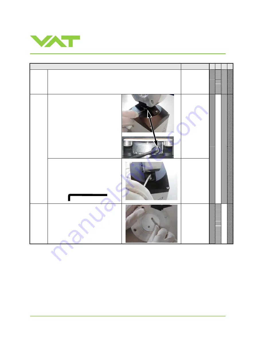
2.  Unfasten clamp coupling. 
 
Note: If you can not access the coupling 
screw, turn plate by hand until you can 
access the coupling screw with Allen 
Wrench. 


Allen Wrench 

2mm 

Re

m

o

ve

 cont

ro

l and actua

ti

ng 

un

it


fr

om val

v

uni

t


3.  Unfasten the 2 connection bolts and 

separate both parts. 


Note: Valve size DN 160 (6”) and bigger 
require a shortened wrench. 
For ordering number refer to «Spare 
parts and accessories». 


Allen Wrench 

3mm 


R

e

move p

lat

4.  Unfasten screws and remove plate 

from shaft. 


Allen Wrench 

3mm 


12 mm 

Summary of Contents for 612 Series

Page 1: ...cated on each product as per the label below or similar made in Switzerland Fabrication No 612 A Fabrication number sample picture Explanation of symbols Read declaration carefully before you start an...

Page 2: ...s or any other reproduction processes nor may it be manipulated with electronic systems duplicated or distributed without written permission from VAT Offenders are liable to pay damages The original V...

Page 3: ...peration 19 3 1 Introduction 19 3 1 1 Local operation 20 3 1 2 Remote operation 20 3 1 3 Safety mode 21 3 1 4 Service indication 21 3 2 Operation under increased temperature 21 3 3 Behaviour during po...

Page 4: ...ating Maintenance Instructions Series 612 DN 25 I D 1 Logic VAT Vakuumventile AG CH 9469 Haag Switzerland Tel 41 81 771 61 61 Fax 41 81 771 48 30 CH vatvalve com www vatvalve com 289700EB 2011 10 21 4...

Page 5: ...30 CH vatvalve com www vatvalve com 289700EB 2011 10 21 5 57 1 Use of product This product is a Butterfly control valve for downstream pressure control in vacuum systems Use product for clean and dry...

Page 6: ...tputs 3 Input voltage Input current Breaking capacity 70 VDC or 70 V peak max 0 5 ADC or 0 5 A peak max 10 W max connector INTERFACE Analog outputs 3 optional 0 10 VDC 1 mA max connector INTERFACE PFO...

Page 7: ...g position Any Control unit for ISO KF version needs support when mounted on horizontal piping and control unit does not hang Wetted materials Body Aluminium AA6082 3 2315 Plate Aluminium AA6082 3 231...

Page 8: ...57 2 Installation 2 1 Unpacking Valves DN63 2 and larger must not be lifted solely by the actuator 2 2 Installation into the system Fingers and objects must be kept out of the valve opening and away f...

Page 9: ...nsor s 2 according to the recommendations of the sensor manufacturer and directives given under Requirements to sensor connection 4 Connect pressure sensor cable 3 to sensor s and then to valve connec...

Page 10: ...of ISO KF flanges Tightening torques for ISO KF flange connections depends on the type of seal which is used Follow recommendations of seal manufacturer 2 4 Admissible forces Forces from the weight of...

Page 11: ...missible forces at controller Attention Do not pushing shocking load or stressing the valve controller Do not deposit anything at valve controller The admissible force at valve controller in regards t...

Page 12: ...nnected to the chamber by a pipe To maintain that the response time is not degraded by this connection it needs to meet the following requirements Inner diameter of connection pipe 10 mm Length of con...

Page 13: ...x B1 min B2 min d1 d2 copper tinned 200 mm 25 mm 25 mm 4 5 mm customized Note Connection plates of ground strap must be total plane for a good electrical contact Note The connection point at chassis F...

Page 14: ...ule SPS that converts 15 VDC from the 24 VDC Concepts External 24 VDC supplied to POWER connector is feed through to SENSOR connector to supply 24 VDC sensors Refer to chapter Power and sensor connect...

Page 15: ...Sensor power wiring via controller Note Use shielded sensor cable s Keep cable as short as possible but locate it away from noise sources Connect the 24 VDC sensors at DB 15 female sensor connector e...

Page 16: ...shielded sensor cable s Keep cable as short as possible but locate it away from noise sources Connect the 24 VDC sensors at DB 15 female sensor connector exactly as shown in the drawing above Do not...

Page 17: ...4 1 Sensor power wiring via controller Note Use shielded sensor cable s Keep cable as short as possible but locate it away from noise sources Connect the 15 VDC sensors at DB 15 female sensor connecto...

Page 18: ...shielded sensor cable s Keep cable as short as possible but locate it away from noise sources Connect the 15 VDC sensors at DB 15 female sensor connector exactly as shown in the drawing above Do not...

Page 19: ...d to the service port for setup and local operation The service port is not galvanic isolated Therefore we recommend using this only for setup testing and maintenance and not for permanent control Ref...

Page 20: ...monitoring basic diagnostic Control Performance Analyzer supports parameter setup manual control sequence control numeric and graphical monitoring data recording data analysis advanced diagnostic When...

Page 21: ...indication This product is able to indicate that the valve unit needs to be cleaned or an obstruction is present A service request is indicated when the control unit detects that motor steps are appar...

Page 22: ...information There is a 4 digit display located on the panel It displays configuration status and position information For details refer to following tables Power up Description Digit 1 Digit 2 Digit...

Page 23: ...de Refer to Trouble shooting for details 3 6 Setup procedure To enable this valve for pressure control setup steps 1 to 5 must be performed In case position control is required only it s sufficient to...

Page 24: ...te It s not possible to do Interface configuration via remote operation 3 6 2 Valve and sensor configuration Basic valve configuration must be adapted according to application needs Definition of valv...

Page 25: ...vacuum system and its operating conditions LEARN must be executed only once during system setup The LEARN routine determines the characteristic of the vacuum system Based on this the PID controller i...

Page 26: ...com www vatvalve com 289700EB 2011 10 21 26 57 Note Sensor signal must not shift during LEARN Wait until sensor signal is stable before LEARN is performed Note Learn may take several minutes Do not in...

Page 27: ...WP pressure of working point Pa qWP CWP pWP CWP required conductance of working point l s qWP gasflow of working point mbar l s pWP pressure of working point mbar qWP CWP 78 7 pWP CWP required conduct...

Page 28: ...nalog inputs and outputs for details 1 Set CONTROL MODE to POSITION CONTROL Select or enter position setpoint 2 Set position SETPOINT Note In case CLOSE VALVE OPEN VALVE or HOLD is also set these have...

Page 29: ...10 21 29 57 Example of PRESSURE and SENSOR READING allocation Above picture shows a 2 sensor system In this configuration sensor 2 covers low range 100 mTorr and sensor 1 covers high range 1 Torr Swit...

Page 30: ...elow Strictly keep the procedure order Required information for support Go to Tools Create Diagnostic File in Control View resp Control Performance Analyzer and save file Pressure flow gas conditions...

Page 31: ...tup Control Parameter Note It s not possible to do Gain factor adjustment via remote operation 3 10 1 2 Sensor delay adjustment Sensor delay adjustment effects Stability Default value is 0 Adjustment...

Page 32: ...the applicable formula depending on units you are familiar with END START SFS RAMP P P P S t t ramptime s PSFS sensor full scale pressure SRAMP setpoint ramp s PSTART pressure start PEND pressure end...

Page 33: ...speed In particular applications it may be of advantage to have a slower valve response Note OPEN and CLOSE are always done with max speed Adjustment procedure 1 Use optimal gain factor sensor delay...

Page 34: ...34 57 3 11 1 Functions and Wiring Note Logic interface allows for remote operation by means of digital and analog signals Digital inputs may be operated either by switches or by voltage sources a Con...

Page 35: ...el 41 81 771 61 61 Fax 41 81 771 48 30 CH vatvalve com www vatvalve com 289700EB 2011 10 21 35 57 b Configuration with voltage source for digital inputs Note Use a shielded cable for analog inputs Do...

Page 36: ...orr Not active 10V 100 10V setpoint 100mTorr Active 10V 10 10V setpoint 10mTorr N A 16 HOLD Digital input 1 This function stops the valve at the current position After release of the signal the valve...

Page 37: ...rrupted by another function with higher priority If on remains established after completion this will not re initiate the function and does also not block functions with lower priorities Note Without...

Page 38: ...eration modes and indicates either that the valve is close or that a service is requested A service request is indicated when the valve requires cleaning due to contamination Configuration of the func...

Page 39: ...e or 10 of sensor full scale In case of 2 sensor operation 10V relates to sensor 1 full scale high range POSITION CONTROL A voltage of 0 10V shall be applied to this input as position setpoint The pos...

Page 40: ...dure Display shows E 22 fatal error rotation angle of valve plate limited during operation Valve plate mechanically obstructed Resolve obstruction Reset control unit Cycle power OFF ON or Send reset c...

Page 41: ...lve configuration for details Sensor voltage shifting Wait until sensor does not shift any more before performing ZERO System pumped to base pressure OPEN VALVE and bring chamber to base pressure befo...

Page 42: ...formed by the customer or has to be carried out by VAT The fabrication number on the valve made in Switzerland Fabrication No A Fabrication number has always to be specified All supplies e g compresse...

Page 43: ...enance period is the lifetime of the vacuum grease being limited under increased temperature In this case grease will separate to PTFE and oil The oil may flow and contaminate the valve parts VAT can...

Page 44: ...the valve from the vacuum system to replace the control and actuating unit Depending on flange screws 2 Unfasten clamp coupling Note If you can not access the coupling screw turn plate by hand until y...

Page 45: ...If only one screw is fasten unfasten the mechanical unit will be damaged Max difference should be less than 1 turn or 0 5 turn of the screws Allen Wrench 3mm Remove and clean mechanical unit 6 Remove...

Page 46: ...f vacuum grease 0 0125 ml 12 Slide both o rings onto shaft till the end 13 Deposit 0 0375 ml vacuum grease between the o rings 14 Clean shaft from vacuum grease Mount mechanical unit to valve body 15...

Page 47: ...om www vatvalve com 289700EB 2011 10 21 47 57 Description Required tool 19 Assemble control and actuating unit to valve unit Tighten mounting screws adequately Allen Wrench 3mm Mount control and actua...

Page 48: ...FO function the option board must be replaced after battery life has expired For ordering number of the modules refer to Spare parts and accessories 5 2 1 Durability of power fail battery The curves i...

Page 49: ...All work on the control and actuating unit has to be done under ESD protected environment to prevent electronic components from damage Top view on control and actuating unit with panel removed Note Al...

Page 50: ...81 771 61 61 Fax 41 81 771 48 30 CH vatvalve com www vatvalve com 289700EB 2011 10 21 50 57 Description Required tool 1 Remove the panel screws Pozidriv screw driver size 1 2 Remove female screw lock...

Page 51: ...d 6 Remove or replace interface board 7 Remove or replace option board 8 Insert master board and interface board in reverse order as disassembled at correct positions see steps 6 5 9 Insert option boa...

Page 52: ...g Maintenance Instructions Series 612 DN 25 I D 1 Logic VAT Vakuumventile AG CH 9469 Haag Switzerland Tel 41 81 771 61 61 Fax 41 81 771 48 30 CH vatvalve com www vatvalve com 289700EB 2011 10 21 52 57...

Page 53: ...re that the appropriate spare parts are supplied 7 1 Control and actuating unit Item Description Valve size Product ordering number All sizes 612 Control and actuating unit 485810 Option board with SP...

Page 54: ...trol Performance Analyzer package for Windows consisting of software and cable 600SP 99LB 000 Control View software for Windows 248126 free download from www vatvalve com or available on order against...

Page 55: ...nd Tel 41 81 771 61 61 Fax 41 81 771 48 30 CH vatvalve com www vatvalve com 289700EB 2011 10 21 55 57 7 4 1 Centering ring with Viton o ring Description Valve size Product ordering number DN 25 1 6122...

Page 56: ...xpense whether consequential special incidental direct or otherwise caused by arising out of or connected with the manufacture delivery including any delay in or failure to deliver packaging storage o...

Page 57: ...n Operating Maintenance Instructions Series 612 DN 25 I D 1 Logic VAT Vakuumventile AG CH 9469 Haag Switzerland Tel 41 81 771 61 61 Fax 41 81 771 48 30 CH vatvalve com www vatvalve com 289700EB 2011 1...

Reviews: