


TECHNICAL INFORMATION
13. Turbopump
VIBRATION ISOLATOR INSTALLATION
Four vibration isolators for ISO and CFF inlet
flange version pumps are available as accesso-
ries.
14. Fan
15. Flexible connection
The four model part numbers are the following:
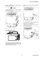
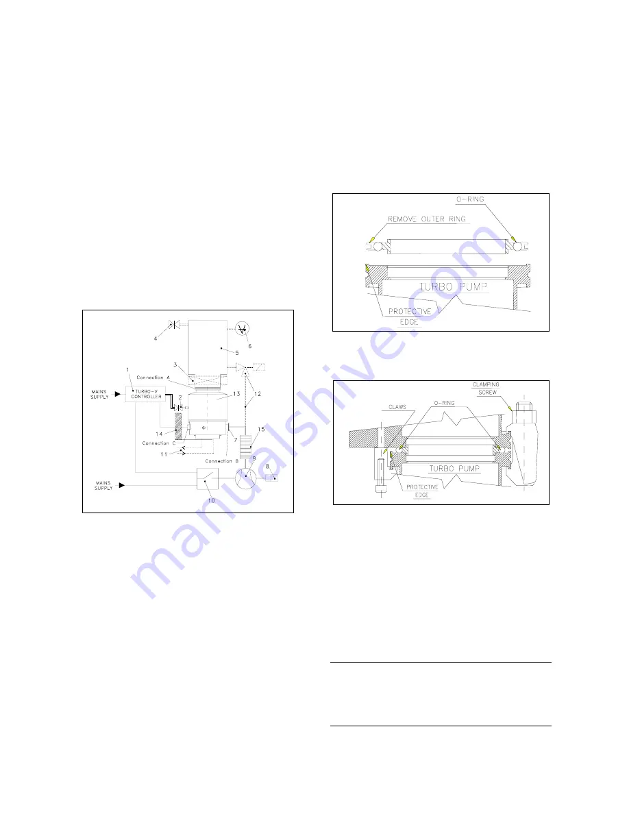
Connection A - HIGH VACUUM FLANGE
−
model 969-9342 for ISO 100 flange;
To connect the Turbo-V550 pump to the ISO inlet
flange, remove the outer ring and position the cen-
tering ring as shown in the figure.
−
model 969-9343 for ISO 160 flange;
−
model 969-9332 for CFF 6” flange;
−
model 969-9333 for CFF 8” flange.
They typically reduce the vibration transmitted
from the Turbo-V550 pump to the system by a fac-
tor of 20.
Please refer to the relevant instruction manual.
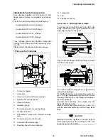
TYPICAL LAYOUT DIAGRAM
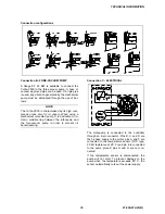
Then fix the two flanges with the clamps or claws
as shown in the figure.
For ConFlat flange connections we recommend
using Varian hardware.
1. Turbo-V
controller
To facilitate assembly and dismantling, apply Fel-
pro C-100 high temperature lubricant to the screw
threads protruding from the flange and between
the nuts and flange.
2. Vent
valve
3. Vacuum pump shut-off valve (optional)
4. System vent valve (optional)
Note that the connections can be made only with
the bolt in the lower side.
5. Vacuum
chamber
6. Ionization
gauge
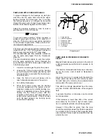
Attach the units and tighten each one in turn. Re-
peat the sequential tightening until the flange faces
meet.
7. Fore-vacuum pump connecting flange
8. Oil mist eliminator
9. Fore-vacuum pump with internal one-way
valve
CAUTION
10. Fore-vacuum pump control relay
Exercise care when tightening nuts and bolts to
avoid creating dents in the envelope as this may
cause the pump rotor to lock.
11. Connection for water cooling
12. Roughing line with valve (optional)
34
87-900-874-01(B)