CB-800
CB-1000
2.5.6 T
RAVEL
S
PEED
S
ELECTION
•
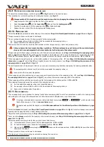
The machine has two travel speeds.
•
Slower
(belt mounted per
Fig. 5
) is suitable for dirt removal. This speed is set at the factory.
•
Faster
(belt mounted per
Fig. 6
) is suitable for snow or leaves removal.
•
The speed is changed by moving the V-belt on the pulleys between the gearbox and the axle (see
Fig. 5
and
Fig. 6
). A sticker is
attached to the top cover of the gearbox showing the positions of the belt in the pulleys on the gearbox and on the axle (see
Fig. 8
).
When changing speeds, the engine must always be switched OFF and the throttle in its
1
STOP position!
1.
Loosen the plastic nut
1
(in
Fig. 7
)
pull the gearbox top cover
2
in the arrow direction, diagonally backwards.
2.
Remove the retaining
cotter pin
3
in
the
lower gearbox cover
4
.
3.
Push on the
lower gearbox cover foot
5
, the cover will release and pop out from the
lower
gearbox cover retainer
4
in
the frame.
4.
Insert your index finger into the hole in the lower cover, slide the cover down towards the ground.
5.
Remove the V-belt from its pulley
6
(in
Fig. 5
or
Fig. 6
) on the axle, towards the left wheel. Then slide the V-belt out of pulley
7
(in
Fig. 5
or
Fig. 6
) on the gearbox towards the right wheel.
6.
Slide the V-belt into the pulley keyway
6
(in
Fig. 5
or
Fig. 6
) on the axle matching the selected gear. Check visually and by
touch that the belt fits correctly in the groove in the selected pulley.
7.
Slide the V-belt into the pulley keyway
7
(in
Fig. 5
or
Fig. 6
) on the gearbox matching the selected gear. Check visually and by
touch that the belt fits correctly in the right pulleys per the selected gear (see
Fig. 5
and
Fig. 6
). The belt must not cross!
8.
Fit the top gearbox cover
2
diagonally under the engine plate, snap it on and tighten the plastic nut.
9.
Slide the lower gearbox cover
5
upwards and insert the
foot
of the lower gearbox cover
5
into the
holder
of the
gearbox lower cover
4
. Insert the retaining
cotter pin
3
into the hole in the
holder
of the lower gearbox cover
4
.
2.5.7 W
HEEL
IDLE
FUNCTION
•
Fig. 9
The wheels can be disconnected from their drive by removing the pin
1
with its retaining ring
2
from one wheel. Only one
wheel is then engaged and the machine can be turned very easily.
Keep in mind that the machine turns ("pulls") on the side where the pin has been removed from the wheel with the
parameters set in this way.
2.5.8 S
ETTING
THE
PRESSURE
OF
THE
SWEEPING
ROLLERS
When the bristle pressure is increased, the reverse movement of the machine is significantly more intense when
the machine travel is switched off and the brush drive is switched on. Therefore, take care for personal safety,
especially in areas with insufficient space behind you.
Always set the bristle pressure on a level, solid surface.
•
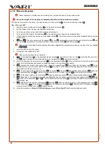
To adjust the brush pressure, use the plastic control knob
4
in
Fig. 3
, protruding from the front plastic cover.
•
By turning the control knob
clockwise
(i.e. to the right), the support wheel retracts into the frame,
increasing
the brush pressure (in
Fig. 10
it is marked as
F +
).
•
By turning the control knob
counter-clockwise
(i.e. to the left), the support wheel extrudes from the frame, the brush pressure
decreases
(in
Fig. 10
it is marked as
F -
).
SETTING:
1.
Set the brushes to the central position
0°
- see
Chap. 2.5.9 Rotating the sweeping rollers axis
on
page 31
and in
Fig. 12
2.
Turn the control knob
4
to set the support wheel first, so it barely touches the ground.
3.
Turn the control knob
4
to set the right pressure:
(a) for dirt or leaves, lying loose on the surface, freshly fallen snow – turn
4 turns
to the right. The wheel is about 2 mm above the
ground.
(b) for dirt firmly staying on the surface (e.g., mud or wet leaves), wet or compacted snow – turn
8 turns
to the right. The wheel is
about 4 mm above the ground.
•
If dirt or snow remains on the surface, you can increase the bristle pressure by turning the control knob further to the right to improve
the machine's performance.
Excessively high bristle pressure results in poor machine control and shortened brush life.
When you have finished working with the machine (e.g., when parking or storing the machine), always extend the support
wheel so that the brush bristles do not touch the mat and are about 2cm. This prevents deformation of the bristle ends.
56
Loosen the plastic nut with about 1 to 2 turns. There is a groove in the cover that allows the cover to be removed without unscrewing the plastic nut.
30
re
vi
ze
1
2/
20
21

