background image

Liquid Level Indicator

4

Installation and Operations Manual

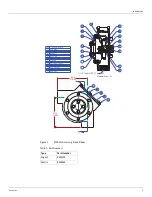
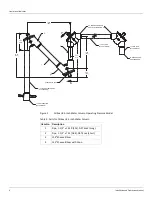
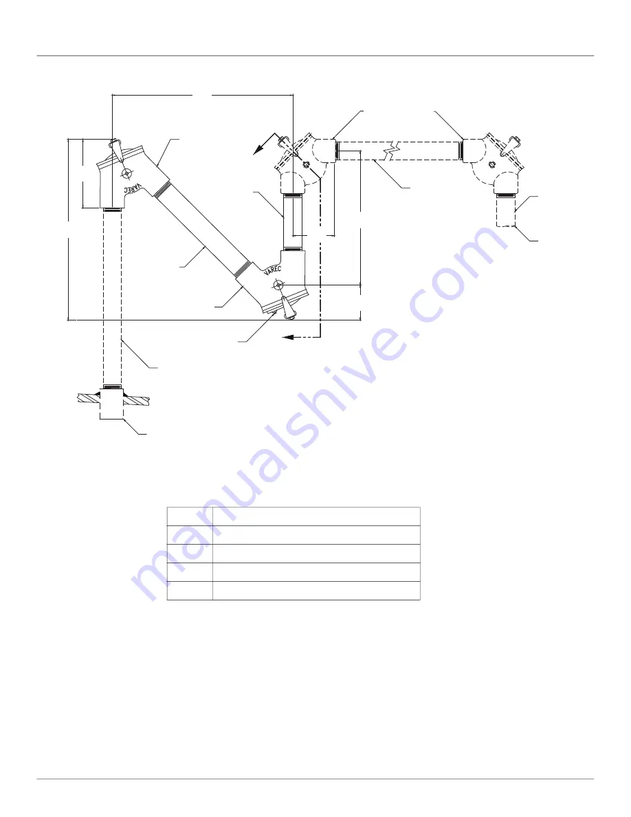
Figure 2:

Oil Seal, 8.5-inch Water Column Operating Pressure Model

1

4

3

2

A

A

90

°

  ELBOW FURNISHED

WITH LEVEL INDICATOR KIT 

7.70
[196]

20.56
 [522]

19.69
 [500]

13.69
 [346]

 4.50
 [114]

 4.06
 [103]

1-1/2 PIPE NPT BOTH ENDS
(BY CUSTOMER)

1/2 NPT DRAIN PLUG

1-1/2 NPT COUPLING
(BY CUSTOMER)

1-1/2 NPT PIPE 
(BY CUSTOMER)

TO GAUGEBOARD
OR GAUGEHEAD 

1-1/2 NPT PIPE 
(BY CUSTOMER)

1

2

3

4

Table 2: Parts for Oil Seal, 8.5-inch Water Column

Item No. Description

1

Pipe, 1-1/2" x 15.50 [394], NPT Ends (Long)

2

Pipe, 1-1/2" x 7.25 [184], NPT Ends (Short)

3

135

°


Sheave Elbow

4

135

°


Sheave Elbow with Drain

Summary of Contents for 6700

Page 1: ...2GVAE1818 Automation Solutions for oil gas defense and aviation applications Installation and Operations Manual Dispatch and 6700 Liquid Level Indicator Accurate gaugeboard indicator for level measure...

Page 2: ......

Page 3: ...2 Phone 770 447 9202 Fax 770 662 8939 Trademarks Acknowledged Varec Inc recognizes all other trademarks Trademarks of other products mentioned in this manual are held by the companies producing them F...

Page 4: ...warranty clause In no case shall the Seller s liability exceed that stated as Limitations of Remedy in the contract between the Seller and Buyer Use of parts that are not manufactured or supplied by...

Page 5: ...Warning Make certain that the tank is empty and not in service Ensure that the tank has been leak and pressure tested as appropriate for the liquid to be stored Observe appropriate safety precautions...

Page 6: ...n cases of rare malfunction Simple apparatus are not to be classified as ATEX equipment or to be marked according to ATEX Directive 2014 34 EU For use in gas groups IIA IIB and IIC Installation Locati...

Page 7: ...Tank Installation Fiberglass Tank 32 Connecting the Tape to the Float 34 Initial Calibration 35 Initial Lubrication 36 Reassembly 37 In service Tank Installations 39 General Preparation 40 Independen...

Page 8: ...55 Standard Installation Kits 55 Standard Float Specifications 55 Bottom Anchor Bar Weight 56 Other Specifications 56 Reference Part Numbers 56 Indicator Part Numbers 57 Float Part Numbers 58 Sheave E...

Page 9: ...hanges in the liquid level in the tank raise or lower the float which moves the indicator cable Cable movement drives the indicator up and down the gaugeboard on the side of the tank The liquid level...

Page 10: ...anufactures accessories for transmitting and telemetering the information to a Varec Data Acquisition System Limit switches may be attached to the Liquid Level Indicator system to provide signaling fu...

Page 11: ...129 Metric BM8564 6 12 155 Section A A 6 12 155 A A 1 1 2 Inch NPT Typical HOUSING 1 FLANGE GASKET HEX HEAD CAP SCREW HEX HEAD CAP SCREW COVER GASKET RETAINING RING RETAINING RING 12 FLANGE CAP CAP GA...

Page 12: ...500 13 69 346 4 50 114 4 06 103 1 1 2 PIPE NPT BOTH ENDS BY CUSTOMER 1 2 NPT DRAIN PLUG 1 1 2 NPT COUPLING BY CUSTOMER 1 1 2 NPT PIPE BY CUSTOMER TO GAUGEBOARD OR GAUGEHEAD 1 1 2 NPT PIPE BY CUSTOMER...

Page 13: ...SHED WITH LEVEL INDICATOR KIT 13 62 346 4 50 114 4 06 103 2 4 1 1 2 NPT DRAIN PLUG TO GAUGEBOARD OR GAUGEHEAD 1 1 2 NPT CARBON STEEL PIPE BY CUSTOMER CUSTOMER REPLACE WITH STAINLESS STEEL PIPE 3 20 56...

Page 14: ...NDS BY CUSTOMER 4 00 102 APPROXIMATE 53 00 1346 1 1 2 NPT PIPE BY CUSTOMER 1 10 52 267 6 00 152 90 ELBOWS FURNISHED WITH LEVEL INDICATOR KIT 3 4 1 2 NPT DRAIN PLUG 1 1 2 NPT PIPE BY CUSTOMER TO GAUGEB...

Page 15: ...ket 2 Hex Nut 3 Hex Head Cap Screw 4 Flat Wsaher Bolt or weld to tank Standard support bracket B14177 003 furnished with gaugeboard 5 75 146 3 4 1 4 2 Reinforcing bracket 02 10721 003 GAUGEBOARD EXTEN...

Page 16: ...float point C as shown below Figure 6 Float Grounding Kit Diagram Float Tape Tape connector Locking Tube Clamp screw 2 required Tape Clamp 2 required Gauging Tape formed into U Avoid bending at hole...

Page 17: ...or toxic materials until a gas free environment is certified Carry breathing equipment when entering a tank where oxygen may be displaced by carbon dioxide nitrogen or other gases Wear safety glasses...

Page 18: ...h that welding cannot be performed the user can construct a support structure with 3 inch 76 mm pipe or conduit close to the outside of the tank The brackets can be welded to the support structure at...

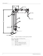
Page 19: ...clude the use of the oil seal accessories see Figure 2 on page 4 and Figure 4 on page 6 If these are to be installed refer to these illustrations as appropriate and perform the following additional in...

Page 20: ...d and install 135 degree elbow 3 onto long pipe 1 4 Apply pipe thread compound and install 90 degree elbow supplied with gauge kit onto short pipe 2 5 Adjust the assembly to provide the tape cable pat...

Page 21: ...on Refer to Table 6 on page 10 See Figure 7 on page 16 for full travel or Figure 8 on page 17 half travel Liquid Level Indicators 1 Determine the position on the tank roof beneath which the center of...

Page 22: ...erior Install a pipe union in the horizontal pipe run in order that the elbows can be easily removed if necessary Then install the horizontal pipe assembly into the tank drop elbow Adjust the length a...

Page 23: ...ine 25 Attach the remainder of the sections to the bottom of the tank Make certain that each section is centered on the chalk line see Figure 7 Note To fit the gaugeboard to the tank cut the highest n...

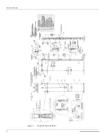
Page 24: ...Liquid Level Indicator 16 Installation and Operations Manual Figure 7 Cone Roof Tank Installation 12 50 318...

Page 25: ...Installation Varec Inc 17 Figure 8 Half Travel Cone Roof Tank Installation 16 50 419...

Page 26: ...ns Manual Figure 9 Gaugeboard Installation Face of gaugeboard Gaugeboard Splice at Support Bracket Tank Wall Chalk Line Tank Wall Chalk Line Support Bracket Detail Half Travel Tank Wall Chalk Lines Fu...

Page 27: ...r cable drive or the combination tape and cable drive that is used to also drive the accessory drive elbow If the tape cable combination is used the cable end goes on the gaugeboard side 28 Lower the...

Page 28: ...ge 16 Half Travel Gaugeboard Remove one side channel from the indicator Position indicator on the gaugehead and reassemble the side channel Thread the cable through the pulley on the indicator Put the...

Page 29: ...l on the tank bottom 3 Cut a 6 inch 152 mm piece of tape from the end inside of the tank Form a U with this piece of tape so there is no hole in the bottom portion of the U Do not kink Figure 12 Tape...

Page 30: ...ity of water 1 0 Note For products of other specific gravities to be gauged adjust the indicator accord ingly Refer to the industry related charts for the particular product With the float just touchi...

Page 31: ...Installation Varec Inc 23 Initial Lubrication Apply a light oil to the elbow and indicator sheaves...

Page 32: ...ce the flange coupling and pipe in a true vertical position may affect the accuracy of the indicator Make sure that the interior of all pipes are clean and free of corrosion 6 After the deck flange an...

Page 33: ...parallel during installation 22 Bolt the gaugeboard support brackets into position see Figure 9 on page 18 The first gaugehead support bracket mounts near the top of the tank The others are spaced at...

Page 34: ...rough the cable crimp and tem porarily tape it to the crimp Note If auxiliary equipment is to be installed do it prior to crimping the cable connector The use of auxiliary units not manufactured or su...

Page 35: ...l on the tank bottom 3 Cut a 6 inch 152 mm piece of tape from the end inside of the tank Form a U with this piece of tape so there is no hole in the bottom portion of the U Do not kink Figure 14 Tape...

Page 36: ...products of other specific gravities to be gauged adjust the indicator accord ingly Refer to the industry related charts for the particular product With the float just touching the bottom of the tank...

Page 37: ...Installation Varec Inc 29 Initial Lubrication Apply a light oil to the elbow and indicator sheaves...

Page 38: ...Liquid Level Indicator 30 Installation and Operations Manual Reassembly 1 Reinstall the covers gaskets and bolts on the elbows 2 Close the tank manholes and inspection covers...

Page 39: ...Installation Varec Inc 31 Figure 15 Bolted Tank Installation 16 50 419...

Page 40: ...rk the position where the bottom cable anchor will be installed 8 Mark the plumb bob string at the height of the tank bench mark This will assure that the plumb bob just touches the bottom when the re...

Page 41: ...to the gaugeboard at a level indication of 2 00 inches 50 8 mm plus the height of the bottom anchor Adjust the cable tension until the float barely lifts from its resting place Crimp the cable connect...

Page 42: ...al more inches fall on the tank bottom 3 Cut a 6 inch 152 mm piece of tape from the end inside of the tank Form a U with this piece of tape so there is no hole in the bottom portion of the U Do not ki...

Page 43: ...fic gravities to be gauged adjust the indicator accord ingly Refer to the industry related charts for the particular product With the float just touching the bottom of the tank water will be at the fl...

Page 44: ...Liquid Level Indicator 36 Installation and Operations Manual Initial Lubrication Apply a light oil to the elbow and indicator sheaves...

Page 45: ...Installation Varec Inc 37 Reassembly 1 Reinstall the covers gaskets and bolts on the elbows 2 Close the tank manholes and inspection covers...

Page 46: ...Liquid Level Indicator 38 Installation and Operations Manual Figure 18 Fiberglass Cone Roof Tank Installation 12 50 318...

Page 47: ...covers the additional procedures that are required for making installations on tanks that are in service Varec service contracts provide the user substantial savings for maintaining and refurbishing...

Page 48: ...Practice 2003 or other appropriate industry or military standard The user provides the 1 5 inch pipe that carries the tape cable and the necessary mounting and support welding The user must drill hol...

Page 49: ...cover to carry the top guide cable anchors 5 Disassemble the inspection cover and gasket from the frame 6 Weld the inspection cover frame to the manhole cover 7 Weld the guide cable anchor nipples and...

Page 50: ...ttings furnished by customer 8 50 216 8 50 216 Detail C 15 75 400 Cover cutout Cover cutout 6 00 152 Detail B Existing Manhole Cover Modifications 10 00 254 19 75 502 3 31 84 18 4 8 Guide cable anchor...

Page 51: ...Installation Varec Inc 43 Figure 20 Severe Service Cone Roof Tank Installation 12 50 318...

Page 52: ...Put a clean drop cloth on the ground and push the tape through a few turns at a time from the drop pipe elbow until the tape cable is unrolled Make sure that the tape cable falling to the ground does...

Page 53: ...e the product under war ranty 17 Install the gaugeboard and indicator Refer to the appropriate tank configuration 18 Set indicator at measured product level 19 Adjust the tape cable tension until the...

Page 54: ...Liquid Level Indicator 46 Installation and Operations Manual Initial Lubrication Apply a light oil to the elbow and indicator sheaves...

Page 55: ...an auxiliary elbow drive adapter kit P N 13 08821 is required The kit contains the English drive elbow P N BM4129 and the tape cable combination P N B7678 106 This has a sprocket sheave that is driven...

Page 56: ...nge 7 Attach the auxiliary unit with adapter flange to the drive elbow ensuring that the sprocket drive pin engages the slotted coupling of the auxiliary unit 8 Refer to the auxiliary unit manual for...

Page 57: ...late Use the spare cable crimp if necessary Normal Operation When the tank is full the indicator is at the bottom of the gaugeboard As the liquid is removed from the tank the float falls and the indic...

Page 58: ...ration Table 7 API Standards API Standard Description 2550 Method For Measurement And Calibration Of Upright Cylindrical Tanks ANSI ASTM D1220 2545 Method of Gauging Petroleum and Petroleum Products A...

Page 59: ...drocarbons vapors or toxic materials until a gas free environment is certified Carry breathing equipment when entering a tank where oxygen may be depleted with carbon dioxide nitrogen or other gases E...

Page 60: ...should be inspected immediately after being placed in service and then daily for the first week Subsequent inspections should be made every 90 days Table 8 The user may adjust the schedule for his ow...

Page 61: ...tuck Yes Check cable path Check for frozen sheave shafts repair replace Check for frozen accessory shafts repair replace No Go to 2 2 Pipes dirty Yes Clean with automotive type spray degreaser No Go t...

Page 62: ...Pulley shaft bushing worn corroded Yes Repair or replace No Go to 4 4 Cable pipe conduit dirty Yes Remove and clean No Go to 5 5 Guide cables loose kinked or broken Yes Tighten repair or replace Tabl...

Page 63: ...olyethylene Half Travel Sheave UHMW Polyethylene Float Cable Type 316 Stainless Steel Float Cable Clamp Type 316 Stainless Steel Float Tape Cable Elbow Drive Kit Type 316 Stainless Steel Gauge Float T...

Page 64: ...or Bar Weight a Other Specifications Table 16 Other Specifications Reference Part Numbers Weight 52 lbs 22 2 kg Material Steel Also available in 304SS and 316SS Operating Range Full Travel 62 ft 23 M...

Page 65: ...Specifications Varec Inc 57 Indicator Part Numbers Table 17 Indicator Part Numbers Part Number Type Service 06 09830 Full Travel All 06 09831 Half Travel All...

Page 66: ...Installation and Operations Manual Float Part Numbers Table 18 Float Part Numbers Part Number Type Service BM9074 000 316 S S Normal Severe BM12338 000 Monel Extreme BM12339 000 Carpenter 20 Extreme...

Page 67: ...9 Sheave Elbow Part Numbers Part Number Description Service 06 08564 Aluminum 90 Normal BM3480 Aluminum 135 Normal BM3481 Aluminum 180 Normal BM4675 Cast Iron 90 Severe Extreme BM4129 Elbow Drive Alum...

Page 68: ...r Bar Weight Part Number Table 20 Bottom Anchor Bar Weight Part Number Part Number Description Service BA4481 Carbon Steel Bottom Guide Wire Anchor Assembly 2 Wire Normal BA4482 005 304SS Bottom Guide...

Page 69: ...All pipes are steel Table 21 Oil Seal Accessory Part Numbers Assembly Part Number Type Service 10 01994 AAA Aluminum Working Pressure 8 5 in W C Normal 10 01994 BAA Iron Working Pressure 8 5 in W C Se...

Page 70: ...Liquid Level Indicator 62 Installation and Operations Manual...

Page 71: ...English Tank to 34 ft F41 English Tank to 41 ft F48 English Tank to 48 ft F55 English Tank to 55 ft F62 English Tank to 62 ft H13 English Tank to 13 12 75 ft half travel H27 English Tank to 27 26 75 f...

Page 72: ...id Level Indicator 64 Installation and Operations Manual M19 Metric Tank to 19 m M21 Metric Tank to 21 m N23 Metric Tank to 23 m Y Special Version N6700 Complete Product Designation Board Type and Len...

Page 73: ......
Page 74: ...62 8939 www varec com 2014 Varec Inc All Rights Reserved This document is for information purposes only Varec Inc makes no warranties express or implied in this summary The names of actual companies a...

Reviews: