Vante 3800, Instruction Manual
The Datex-Ohmeda 3800 is a dependable medical device designed for professional use. Featuring advanced technology, this user-friendly device ensures accurate patient monitoring. To better understand its functionalities, a comprehensive Manual is available for free download at manualshive.com. Start your hassle-free manual download now!
Share
Download


Reviews:
No comments
Related manuals for 3800
V70
Brand: DANICUB Pages: 14
603
Brand: B&G Pages: 2

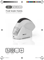
SLIM
Brand: OBH Nordica Pages: 60
4s2
Brand: 4titude Pages: 25
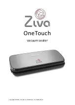
OneTouch
Brand: ziva Pages: 21
7952
Brand: OBH Nordica Pages: 64
EASY
Brand: GD Import Pages: 8
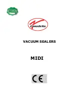
OMNIA
Brand: Janschitz Pages: 9
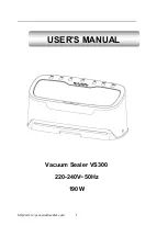
VS300
Brand: Yeasincere Pages: 15
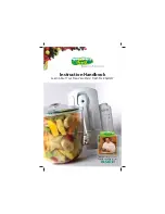
Fresh
Brand: VacuWare Pages: 13

Home Base
Brand: Vacuvita Pages: 32
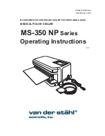
MS-350 NP Series
Brand: Van Der Stahl Pages: 42
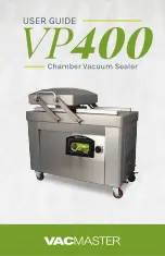
VP400
Brand: Vacmaster Pages: 24
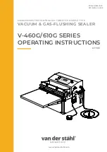
V-460G Series
Brand: Van Der Stahl Pages: 116
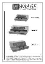
SV-FOOD
Brand: WAAGE Pages: 16
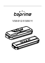
VS6611
Brand: toprime Pages: 36
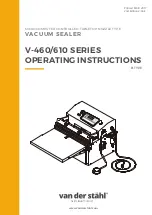
V-460 Series
Brand: Van Der Stahl Pages: 76
EV103
Brand: Jata electro Pages: 12


