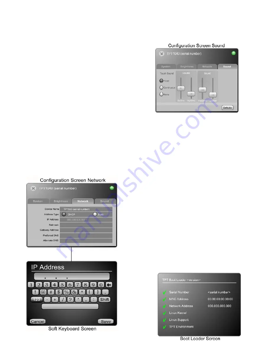
Network
The Network screen allows setting the screen name and setup
of an IP address for the TPT1040. As with most IP based
products the TPT1040 may obtain an IP address automatically
using the DHCP setting. It is also possible to assign a Static IP
address which may be more desirable for most applications.
The current IP address, DHCP or Static, is displayed on this
screen.
Device Name
The “Device Name” is the name that will identify the TPT1040
in Design Center for exporting. It may be changed from
“TPT1040 (serial number)” to whatever is desired. It is
recommended that the name match the name used in Design
Center.
•
To enter the name, simply touch the Device Name
section of the table to open the soft keyboard screen
then enter the name and touch Save.
DHCP
•
To set a DHCP address, simply click the DHCP button
and then click the X to exit the configuration screen.
Static
•
To set a Static IP address, simply click the Static button
and then click on the IP Address section of the table.
•
A soft keyboard is opened allowing the static IP address
to be entered.
•
Click Save when finished
•
Additional IP settings are also available for more
advanced network configurations
o
Netmask
o
Gateway Address
o
Preferred DNS
o
Alternate DNS
Use a DHCP or assign a Static IP address. Try to keep the
TPT1040 on the same network as the InFusion Controller.
Sound
The Sound configuration screen allows changes in Volume,
Frequency and Duration of pulse or Continuous sound when the
screen is touched. The Volume levels may be adjusted for Daytime
and Nighttime using the same programming as mentioned in the
Brightness
section above. Experiment with settings on this screen
to obtain a desired sound for buttons.
Front Of TPT1040
On the front of the TPT1040 are two hard buttons that may be
assigned to any task in Design Center like a keypad button.
There is also a built-in Light sensor and Motion sensor, behind
the translucent diffuser in the front, bottom center of the
screen. To set these up, see the
Brightness
section above. The
two very small holes on each side of the Sensor lens balance
the design. The left hole contains a Reset button.
Note: the Reset button requires a long – 1
¼
” – straight piece of
wire, e.g., a straightened paper clip would be ideal. The hole
contains a plastic tube to guide the wire preventing it from
wandering when inserted to reset the station.
Video/Audio Connections
A/V connector cables are available from Vantage, part number
VDA-0176. To build your own A/V connector cables please
study drawings below. CAT-5 wire should be used when
building A/V cables. Note: A/V cables should not exceed
200ft.
Reset
To reset the TPT1040 to
Boot Loader Screen
(below) while
holding in hard buttons 1 and 2, press and release the Reset
button in the right hole. Do this if the screen is in an unstable
mode and communication cannot be established. When the
screen boots to the
Boot Loader Screen
communication should
be possible again allowing firmware updates. Pressing Reset
without holding buttons 1 and 2 simply resets the screen. Also
see
Trouble Shooting Tips
below.
Boot Loader
The Boot Loader screen is a root level boot screen and may be
used when simply communicating with the screen at a
rudimentary level (Touchscreen Designer Exports are not
possible while in this mode). It also displays a green checkmark
or red X for each section of the TouchScreen’s operational
status. This is valuable for troubleshooting. Reset the screen to
exit the Boot Loader Screen.


