Vanner Power Group
SP00155 BATTERY CHARGER—OWNER'S MANUAL
V a n n e r P o w e r G r o u p
— 3 —
3B)
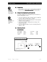
3B) Charger Mounting
Charger Mounting
• Install Charger in horizontal position, (mounting brackets are attatched to
the unit). This unit requires airflow under chassis for proper cooling.
3C)
3C)
Routing and Connecting Battery Charger DC Output Cables
Routing and Connecting Battery Charger DC Output Cables
This Charger is designed for 24 VDC applications only. If connected to non-
specified voltages, damage will result.
1.
Connect the Charger's RED cable to the battery positive (+) terminal and
the BLACK cable to the battery negative (-) terminal.
2.
Battery cable connections must be clean and secure to minimize electrical
resistance for optimum performance.
3.
Route and secure charger DC cables away from Hot, Sharp, or Hard
surfaces and components.
4.
Ground the charger case properly. The unit is not grounded through the
negative DC cable.
3D)
3D) Battery Charger Parts List
Battery Charger Parts List
Vanner Part Numbers
Vanner Part Numbers
Circuit Breaker:
07485
Cooling Fan:
07668
PCB Assembly:
D08438
Relay:
06606
Capacitor:
05083
Rectifiers:
04898
W
WARNING
ARNING
Safety goggles
should be worn
when working with
or near batteries.
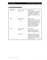
Max Battery Charger Wiring Diagram
W
WARNING
ARNING
Battery connections
must pass a
minimum of 50
amps.
55


