Vanguard Instruments II Series Operating Instructions Manual Download Page 20


ATO-

250™ Operating Procedures 


16 

a. 

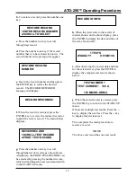
On the second SETUP menu, press the 

number three key (RESTORE RECORD), to 
display the menu: 


b. 

When the ERASE RECORD menu is 

selected, the above menu displays.  Press the 
number one key to erase a single record. 
 

c. 

If all records are to be erased, press the 

number two key. An advisory note, ALL 
RECORDS ERASED! will display next and 
the unit will return to the START-UP menu. 
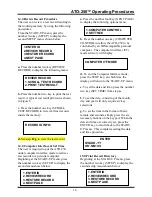


c. 

Key in the record number to be erased 

then press the ENTER key to confirm.  The 
following advisory displays: 


d. 

Press the ENTER key to return the 

display to the START-UP menu.   


This completes the restore record procedure. 

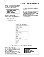
17.0 Calibration Check procedure 

Calibration check allows the user to verify 
the electronics of the ATO-250 is working 
properly. 
All of the procedures start at the START-UP 
menu, shown below: 


a. 

Press the number three key to begin the 

CAL CHECK procedure. The instructions 
for the next step will display as follows: 
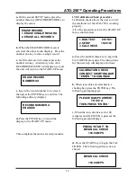


b. 

When test cables are attached to a 

shorting bar, press the ENTER key. The 
following prompt appears: 


c. 

When the test current is set to 100 

Amperes and the ENTER is pressed, the 
following prompt displays: 


d. 

Press the START key to begin the CAL 

CHECK. The following advisory note is 
shown: 


ERASE RECORD 
1. ERASE SINGLE RECORD 
2. ERASE ALL RECORDS


ERASE RECORD 
NUMBER:

XX


RECORD NUMBER 

ERASED! 


1.RUN TEST         05/15/01 
2.SETUP              10:28:03 
3.CAL CHECK 

CALIBRATION CHECK 
CONNECT SHORTING BAR 
“ENTER” TO CONTINUE


PLEASE RAMP CURRENT 

TO 100 A 

THEN PRESS 

“ENTER”


PRESS “START” TO 

BEGIN CAL CHECK 

100.0 AMPS 

BEGIN CAL CHECK 


100.0 AMPS


Summary of Contents for II Series

Page 1: ...S for the MODEL ATO 250 10 250 Amperes Digital Micro Ohm Meter Series II ID Number VIC 25000 S2 Vanguard Instruments Company 1710 Grevillea Court Ontario California 91761 TEL 909 923 9390 JULY 2001 FA...

Page 2: ...isk of introducing additional or unknown hazards To ensure that all designed safety features are maintained it is recommended that repairs be performed only by Vanguard Instruments Company factory per...

Page 3: ...s 2 6 0 Controls and Indicators 3 7 0 Preset Setup 5 8 0 ATO 250 Printer Paper 6 9 0 ATO 250 Cable Connections 6 10 0 Operating Procedures 8 11 0 Run Test Procedure 8 12 0 Enter Test Information Proce...

Page 4: ...5 Figure 4 0 ATO 250 Cable Connection 6 Figure 5 0 Step by Step Operating Procedures 7 Figure 6 0 Typical ATO 250 Test Report 11 Figure 7 0 Typical Test Record Directory Print Out 15 Figure 8 0 Bus Ba...

Page 5: ...ows based software package is supplied with each ATO 250 that allows the user to retrieve test records stored in the unit s memory Operation requires little more than connecting the test leads to an u...

Page 6: ...hm meter POWER 85 to 132 Vac or 200 240 Vac selectable 50 60 Hz SIZE inches 16 8 wide by 12 6 high by 10 6 deep WEIGHT Less than 42 lbs TEST CURRENT 10 to 250 amperes READING RANGE 1 micro ohm to 300...

Page 7: ...mber is cross referenced to a functional description in Table 2 0 Although the purpose of these controls and the display may seem obvious and intuitive users should become familiar with them before at...

Page 8: ...el from 10 to 250 Amperes 7 None 4 line by 20 character backlit LCD screen Use for displaying menu selections prompts and test result data 8 None Keypad consisting of momentary contact pushbuttons Ten...

Page 9: ...ction is set by jumpers on a terminal block as shown in Table 3 0 and in Figures 2 0 and 3 0 Table 3 0 Input Power Voltage Selections VOLTAGE SELECTION TERMINAL BLOCK JUMPERS 90 130 Vac Brown to Blue...

Page 10: ...nt Co 13607 E Trent Avenue Spokane WA 99216 Tel 509 893 9881 Fax 509 893 9803 Part Number TP 3 paper 9 0 ATO 250 Cable Connections The ATO 250 is supplied with a set of 35 foot test cable Each cable c...

Page 11: ...ATO 250 Operating Procedures 7 Figure 5 0 Step by Step Operating Procedures...

Page 12: ...setup for 240 volt operation plug the power cable into a 240 volt outlet receptacle b Insert the test current cable plugs and the test voltage sensing cable plugs into the respective control panel ja...

Page 13: ...Figure 6 After the test result is printed the KEEP THIS READING prompt will appear If a printout of the test record is not needed then press the number two key NO in which case the following prompt i...

Page 14: ...TEST then the SAVE THIS RECORD display is shown next o To save the record into the FLASH EEPROM select the number one key YES The ATO 250 will assign a record number automatically as shown below p Th...

Page 15: ...key once to select the number 2 Press the key a second time to select the letter A If the key is pressed a third time letter B will be selected While the fourth time will select the letter C Pressing...

Page 16: ...ers for the SERIAL NUMBER Then press the ENTER key The KVA RATING prompt will display i Press the characters of the KVA RATING Then press the ENTER key The OPERATOR ID prompt appears next j Place the...

Page 17: ...ich will printout the test record and return to the START UP menu h When the list scrolls to the record of interest shown on the above display press the ENTER to display the date and time of the test...

Page 18: ...ER CONTROL to allow the ATO 250 to be controlled by an IBM compatible personal computer The computer interface ITF mode advisory will display d To end the Computer Interface mode press the STOP key at...

Page 19: ...printout the display returns to the START UP menu A typical test record directory print out is shown in Figure 7 0 Figure 7 0 Typical Test Record Directory Print Out 16 0 Erase Record Procedure The fo...

Page 20: ...allows the user to verify the electronics of the ATO 250 is working properly All of the procedures start at the START UP menu shown below a Press the number three key to begin the CAL CHECK procedure...

Page 21: ...s the following test results will display in rapid succession f Press the ENTER key to return the display to the START UP menu This completes the CAL CHECK procedure Figure 8 0 Bus Bar Connection ZERO...

Page 22: ...urrent teeth are touching the device under test DUT 2 Inspect sensing cables 2 No Test Current Current reads zero and resistance reading is also zero 1 No test current going through the DUT 2 Drive ci...

Page 23: ...Operating Procedures 19 APPENDIX B ATO 250 Cable Accessories Plastic Quick Disconnect Clip C Clamp Current Connector and Sensing Wire Connector C Clamp Plastic Clip Current Connector Sensing wire Con...

Page 24: ...ATO 250 Operating Procedures 1710 Grevillea Court Ontario CA 91761 USA Phone 909 923 9390 Fax 909 923 9391 Website http www vanguard instruments com ATO 250 11 05 01 OAK...

Reviews: