background image

RS−P Solar Water Pump Controller        User Manual 


Chapter 2    Use and installation of PS-P Solar water pump controller 

17 


2.7 Installation process


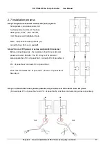
Step 1 Prepare accessories of solar AC pump system. 

Solar panels, visor,solar stands, AC   
3-phase pump inverter, AC 3-phase 
380V pump, wires, 

DC breaker,   

AC breaker and installation tools.   

 
Note: 

Accessories are optional, you   

can either buy from us or yourself. 


Step 2 Connect PV panels in series and parallel like below: 

Before connecting wires , the customer should cover all solar   
panels with visor for safe. The PV Array is of N pieces of 
solar panels.then PV+ of panel No.1 connects PV- of panel No.2 


PV+ of panel No.2 connects PV- of panel No.3; 

……


Then rest two cables PV- of panel No.1 and PV+ of panel No.N   
See step 4. 


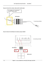
Step 3. Cut the black outer plastic protective layer of the rest two cables from PV panel.   

(For example, PV- of panel No.1 and PV+ of panel No.N) And then connects long wires respectively. 


Cut 

Cut   

Summary of Contents for RS-P-4D2500

Page 1: ...RS P Solar Water Pump Controller User Manual ...

Page 2: ...ere accident or loss safety measures such as redundancy or bypass shall be taken Goods Arrival Inspection Note Note If the controller is found damaged or have missing parts the controller cannot be installed Otherwise accident may be caused Installation Note Note When handling and installing the controller please hold the controller bottom Do not hold the enclosure only Otherwise your feet may be ...

Page 3: ...2 and W T3 otherwise the controller will be damaged It is forbidden to connect the controller output terminals to the capacitor or LC RC noise filter with phase lead otherwise the internal components of the controller may be damaged Please confirm that the power supply phases rated voltage are consistent with those indicated by the nameplate otherwise the controller may be damaged Do not perform d...

Page 4: ...sink and the braking resistor have high temperature Please do not touch such device otherwise you may be burnt When the controller is used by crane or lifting equipment mechanical contracting brake shall also be equipped Please do not change the controller parameter randomly Most of the factory settings of the controller can meet the operating requirement and the user only needs to set some necess...

Page 5: ...ecautions Note Note The circuit boards have large scale CMOS IC Please do not touch the board to avoid the circuit board damage caused by ESD Others Danger Danger It is forbidden to modify the controller unauthorizedly otherwise human injury may be caused ...

Page 6: ...nd Space 8 2 4 Product Outline Mounting Dimension and Peripheral Devices 9 2 4 1 Product Outline Mounting Dimension and Weight 9 2 4 2 Wire connection 10 2 5 Operation Panel Outline 12 2 6 Terminal functions 15 2 7 Installation process 17 Chapter 3 Wells water towers working mode 20 Chapter 4 Routine Repair and Maintenance 22 4 1 Routine Maintenance 22 4 2 Periodic Maintenance 23 4 3 Component Rep...

Page 7: ...gy which not only cuts the cost but also protects the environment RS P PV Pump Controller can directly drive various kinds of 3 phase asynchronous motor with high power integration and less components which improves the system reliability RS P Solar Water Pump Controller Power PV Pump Motor 1 2 water pump selection Water pump select based on how many water need per day and the actual water height ...

Page 8: ...S P Solar Water Pump Controller User Manual 2 Chapter 1 System configuration 1 3 solar panels selection Solar Array Circuit breaker Full water induction Water shortage induction WELL x5 com com TANK x4 M ...

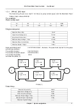
Page 9: ...er Voltage Vpm 120 8V Maximum Power Current Ipm 1 08A Maximum System Voltage 1000V Solar panel total power 0 37 2 1000 740W Remark The power ratio can be1 5 in the place with strong sunshine The number of panel 740 130 5 69 6 The number of tandem repeat 310 120 2 58 3 The number of parallel 6 3 2 As follow the picture 1 Picture 1 Solar Array Maximum Power Pm 780W Open Circuit Voltage Voc 465V Shor...

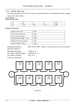
Page 10: ...r Pm 130W Open Circuit Voltage Voc 155 0V Short Circuit Current Isc 1 28A Maximum Power Voltage Vpm 120 8V Maximum Power Current Ipm 1 08A Maximum System Voltage 1000V Solar panel total power 0 55 2 1000 1100W Remark The power ratio can be1 5 in the place with strong sunshine Solar panel total power 1100 130 9 The number of tandem repeat 540 120 4 5 5 The number of parallel 9 5 1 8 2 As follow the...

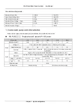
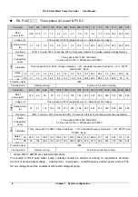
Page 11: ... Single phase AC power PV DC power Power W 600 800 1200 1700 2500 MotorPower kW 0 55 0 75 1 1 1 5 2 2 Outpu Voltage V Three phase AC 220V adjustable area 0 Rated Input AC voltage Rated current A 2 9 4 5 6 0 7 5 10 Overload 150 1 minute 180 10 seconds 200 0 5 second interval 10 minutes inverse time lag feature Input Rated Single or Three phase 200 240V 50Hz 60Hz PV Area VocDC410V 30V Allowable AC 1...

Page 12: ...28V Voltage imbalance 3 allowable frequency fluctuation 5 MPPT Area DC520 650V Rated Current A AC 1 9 2 8 3 9 4 2 6 1 9 4 9 9 14 3 18 7 24 2 26 4 33 42 9 49 5 66 DC 2 1 3 0 4 2 4 6 6 6 10 2 10 8 15 6 20 4 26 4 28 8 36 46 8 54 72 Protection class IP20 Cooling mode Natural cooling Forced air convection cooling Power W 40K 47K 66K 77K 100K 120K 140K 170K 210K 230K 270K 280K 330K 400K 450K Motor power...

Page 13: ...r 7 Chapter 2 Use and installation of PS P Solar water pump controller 2 1 Product Model Description The digits and letters in the product model field on the nameplate indicate such information as the product series power supply class power class and software hardware versions 2 2 Product Nameplate Description ...

Page 14: ...le materials such as wood Keep the drilling scraps from falling into the controller during the installation Mount the controller vertically in the electric control cabinet mount the cooling fan or air conditioner to prevent the ambient temperature from rising to above 45 ºC For the sites with adverse environment it is recommended to mount the controller heat sink outside the cabinet 2 3 2 Mounting...

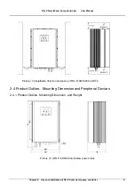
Page 15: ...llation of PS P Solar water pump controller 9 Picture 4 Installation direction and space of RS P 4D3600 to 4D17k 2 4 Product Outline Mounting Dimension and Peripheral Devices 2 4 1 Product Outline Mounting Dimension and Weight Picture 5 RS P 4D5000 and below power class ...

Page 16: ...00 to 4D2500 236 350 160 220 270 4 8 5 6 RS P 2D600 to 2D800 RS P 4D3600 4D5000 236 350 160 220 270 15 5 8 5 8 RS P 2D1200 2D1700 RS P 4D6600 260 410 186 244 326 30 8 5 10 RS P 4D7700 RS P 4D12k 300 491 216 284 405 60 9 15 RS P 4D17k RS P 4D21k to 4D450k Customized according to user requirements 2 4 2 Wire connection 1 Parts of installation specification The specification is fixed with screws GB90...

Page 17: ...ontroller and Peripheral Devices The customer can select devices with according to the site condition Power supply Input AC reactor DC reactor controller Grounding Output noise filte Output AC reactor Motor Grounding Picture 7 Circuit breaker or RCCB RCCB Contactor Input noise filter Solar supply Pv distribution box Contactor DC reactor ...

Page 18: ...pacitor or load with silicon control at the same power node there will be high peak current flowing into input power circuit which damages the rectifier components When the voltage imbalance of the three phase power supply of the controller exceeds 3 the rectifier component will be damaged It is required that the input power factor of the controller shall be higher than 90 When the above situation...

Page 19: ...h Energy Indicator Bright display energy generated by the solar panel red Control panel Hz A Rotation rate Indicator Bright display rotation rate Flash display preset rotation rate green Hz V Percent Indicator Bright parameter is in percentage terms green Hz A V Time Indicator Bright parameter is time green No unit Indicator Dark parameter is no unit value State Indicator light Standard three key ...

Page 20: ...er PX YZ decrease at the edit bit 2 When is in second menu parameter s value decrease 3 When is in STOP RUN state preset frequency or preset closed loop decrease Shift key 1 When is in first menu use Shift key change PX YZ edit bit 2 When is in second menu use Shift key change parameter s value edit bit 3 When is in STOP RUN state use Shift key change display parameters e g frequency current volta...

Page 21: ...ter with Control panel examples 1 Set H0 05 220 PRG 1 2 3 2 2 PRG 1 1 1 6 PRG ESC 2 Set P9 02 2780 PRG 2 9 2 2 2 PRG 1 1 2 3 PRG ESC 2 6 Terminal functions Picture 10 Wiring of terminals 0 00 P0 00 P0 00 H0 00 H0 00 280 280 380 380 H0 05 220 H0 06 0 00 0 00 P0 00 P0 00 P9 00 P9 00 2750 2750 280 2850 2850 P0 02 2780 P0 03 0 00 ...

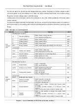
Page 22: ...l of water tower X5 sensing terminal of well Com common terminal X1 to X7 DI Multi function input or pulse input Input specification 24VDC 20 5mA 0 to 200Hz Extern al RS485 CN7 RS485 for operation panel Max cable length between the host computer and RS485is 15m RS485 GND Shielded layer of COM RS485 is grounded Baud rate 4800 19200 38400 57600bps AI 10V AI reference voltage 10V 3 10mA maximum outpu...

Page 23: ...r buy from us or yourself Step 2 Connect PV panels in series and parallel like below Before connecting wires the customer should cover all solar panels with visor for safe The PV Array is of N pieces of solar panels then PV of panel No 1 connects PV of panel No 2 PV of panel No 2 connects PV of panel No 3 Then rest two cables PV of panel No 1 and PV of panel No N See step 4 Step 3 Cut the black ou...

Page 24: ...f PS P Solar water pump controller Step 4 Connect the rest two cables with circuit breaker Step 5 Connect circuit breaker and solar pump controller For example PV of panel No 1 and PV of panel No N Connecting controller DC Solar panel DC Breaker DC Connecting controller DC Breaker ...

Page 25: ...st for the reference Connect PE wire of pump and PE cable of pump controller Connect V wire of pump and V cable of pump controller Connect W wire of pump and W cable of pump controller Connect U wire of pump and U cable of pump controller Step 7 Re check wiring connection of solar pump system If everything is ready correct wiring enough output power of PV arrays and etc then switch ON DC breaker a...

Page 26: ... sensing cable close is full of water effectively yes other is inactive No Dry state sensing lines short for the dry state is invalid NO off to the dry state valid yes The controller can run only under the condition of no full in tower and no short in well Remark 1 The controller can automatically run delay of 30s under the condition of run 2 The controller can automatically off delay of 30s under...

Page 27: ...dled according to the logic When used alone tower water level sensors Well and Well wire shorting should be in the state on behalf of the wells do not dry When used alone wells water level sensors Tank and Tank wire should be in the OFF state the water is not pumped full of representatives towers the pump dry dry run protection Open the tower well protected mode control RS P solar water pump contr...

Page 28: ...ble below Item Inspection Contents Inspection Means Criteria Operating Environment Temperature Thermometer 10 40ºC Derated at 40 to 50ºC and the rated output current shall be decreased by 1 for every temperature rise of 1ºC Humidity Humidiometer 5 95 no condensing Dust oil water and drop Visual check There are no dust oil water and drop Vibration Special test instrument 3 5m s2 2 9Hz 10m s2 9 200H...

Page 29: ... 500VDC megameter Normal 4 3 Component Replacement Different types of components have different service lives The service lives of the components are subject to the environment and application conditions Better working environment may prolong the service lives of the components The cooling fan and electrolytic capacitor are vulnerable components and shall be conducted routine inspection as per the...

Page 30: ...nt protection when deceleration operation Low grid voltage Check proper input voltage and power supply Too big rotating inertial of load Choose appropriate energy braking components Improper setting of motor parameters select proper power or controller Deceleration time is too short Prolong deceleration time Power level of controller is small Replace with controller with proper model 3 E oc3 Over ...

Page 31: ...erature protection Ambient over temperature Lower the ambient temperature and strengthen ventilation and heat dissipation Blockage of air duct Clean the dusts wools and other foreign objects in the air duct Fan failure Check whether fan wirings are well connected Replace a new fan of the same model controller module failure Seek for technical support Temperature detection circuit failure Seek for ...

Page 32: ...ion missing connection or disconnection at the power terminal of the controller Check the power connections as per the operational regulations and eliminate the errors of missing connection and disconnection Serious imbalance of input power at three phases Check whether the imbalance of input power at three phases comply with the requirements Burning of capacitor of the controller Seek for technic...

Page 33: ... check sum is correct and whether the receiving and transmission interval complies with the requirements The controller is set to master mode Set the controller to slave mode 29 E SE2 Communicatio n abnormal 2 RS485 terminal The communication of RS485 terminal is disconnected Check the connection of the equipment communications The baud rate is set improperly Set compatible baud rate The communica...

Page 34: ...ection Load failure Check whether motor is blocked Replace controller with proper model Input failure Check whether there is phase loss Output failure Check whether there are phase loss or short circuit 35 nULL Pump protection against running without water Pump runs without water motor cable connection is abnormal Check water level or pipes and check cable connection Motor protection against zero ...

Page 35: ...f the controller after power off completely check 10V to GND connection between Ω resistance value is less than 5K 4 why controller E P10 abnormal faults A please check whether the controller panel 10V below 9Vor above 11V if the controller is completely power down after check 10Vto GND connection between Ω resistance value is less than 5K 5 485 why PLC and controller communication is not normal A...

Page 36: ...ler 55KW 75KW power level controller fan is not controlled the electricity is running power of 90KW and above level controller fan operation is running commands radiator temperature controller and common control the electric fan does not run at low temperature controller but when the controller or the radiator at high temperature fan running 9 Control panel CN1 ribbon cable loosening or damage of ...

Page 37: ...wind abnormal voltage salt corrosion gas corrosion or nature destroy or other force majeure reasons lead to the fault F The damage happens during the installation or delivery G Without the authority of the manufacture the customer disconnect the parts or change the constructure or circuit H The fault happens because of the wrong maintain etc deformation destroy scoring and so on I Tear up or destr...

Page 38: ...le by favorable Once the customer sign the contract about maintenance confirm with signature and understand maintenance clause 3 5 Maintenance freight A During the warranty period the customer should bear the fright of sending to the manufacture and the fright of back will be borne by the manufacture B If the customer require urgently delivery through express coach or air express or send to the as...

Page 39: ...e customer and will notice for supplement to the customer before using up If not on site servicer have the right to back and do not take the responsibility meanwhile the manufacture have the right to reject on site aftersales service for the customer again E Validity of on site service The manufacture service staff will go to the site of the Mainland Chinese by public transport within 48 hours But...

Page 40: ...ovision of the After sales Service Regulation V T ShenZhen V T Technologies Co Ltd RS P Solar Water Pump Controller Package List No item Unit Number Remark 1 Controller piece 1 2 Cable set 1 3 User Manual piece 1 4 Warranty card piece 1 5 Certification piece 1 6 Package material set 1 REMARK For the safety of your propriety please check the association according to package list and operate before ...

Page 41: ...rgent normal Customer Name Feedback time day Month year Customer Connector Connector telephone Marketing staff Confirming time Description simple and answer the follow three problems 1 What is happen to the Controller and is it the first time If not please descripte the ex service 2 Mchine mold and code 3 Main Problem 4 Connection Department Check Time ...

Page 42: ...pecial inverter Tool servo drive Port crane special inverter Hybrid electro hydraulic servo driver Air compressor inverter Mine winch special inventer Integration drive injection molding machine Paper industry special inverter Water supply special inverter Stone processing industry specific inverter Textile spinning special inverter Ceramic industry special drive 3200Hz high frequency special inve...

Reviews: