background image

www.vanco1.com

 800-626-6445

6

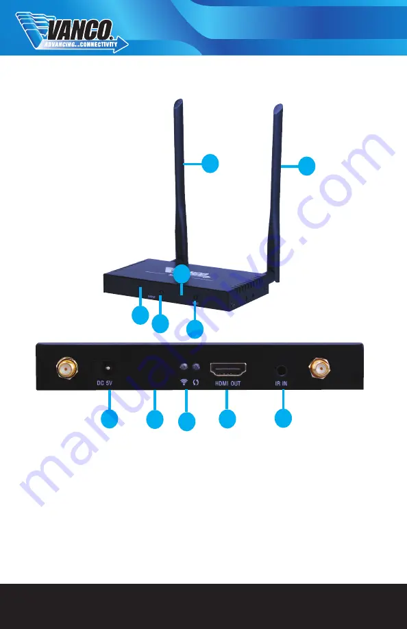
PANEL DESCRIPTIONS

RECEIVER


1.  Antennas
2.  RF Channels (Selectable 0-9 to “marry” to Transmitting unit; other Receivers can be set to the same RF 

channel to split signal)

3.  Channel Toggle Switch (will change RF Channels 0-9 sequentially)
4.  IR Sensor (for included remote to change to RF channels remotely)
5.  Reset Button
6.  DC 5V Power Supply Port
7.  Signal Status Indicator (Solid Green for successful signal when connected to source)
8.  Syncing Status (Blinking Green when connected to Receiving unit; Solid Green will appear if no connection 

to Receiver)

9.  HDMI OUTPUT (Connect to an HDMI display)
10. IR IN (Connect included IR Receiver (RX) and place near or at display for IR control)

1

6

7

8

10

1

2

3

5

4

9

Summary of Contents for HDWIRKIT

Page 1: ...HDMI WIRELESS EXTENDER RECEIVER Vanco Part Number HDWIRKIT HDWIR RX Technical Support www vanco1 com techsupport vanco1 com 800 626 6445...

Page 2: ...ularly at the plugs 9 Use unit only with accessories specified by the manufacturer 10 Refer all servicing to qualified personnel CAUTION HDMI is a very complex technology requiring continuous authenti...

Page 3: ...ontrol the source from any display location connected With the ability of sending HDMI signals wirelessly whether point to point or splitting to multiple displays the HDWIRKIT and optional HDWIR RX ar...

Page 4: ...0Hz 720p 50 60Hz 1080i 50 60Hz 1080p 50 60Hz Supports Audio Formats L R stereo audio Maximum Transfer Rate 10 2 Gbps Input and Output TMDS signal 0 5 1 5Vp p TMDS Input and Output DDC signal 5Vp p TTL...

Page 5: ...5V Power Supply Port 7 HDMI INPUT Connect to an HDMI source 8 Signal Status Indicator Solid Green for successful signal when connected to source 9 Syncing Status Blinking Green when connected to Rece...

Page 6: ...ensor for included remote to change to RF channels remotely 5 Reset Button 6 DC 5V Power Supply Port 7 Signal Status Indicator Solid Green for successful signal when connected to source 8 Syncing Stat...

Page 7: ...h power supplies to the TRANSMITTER and RECEIVER using the provided power supplies TRANSMITTER first followed by RECEIVER 7 Using the manual toggle buttons on the units or the provided IR remote contr...

Page 8: ...rce see below for placement tips IR BLASTER TX To control the source plug IR Blaster into IR OUT port of TRANSMITTER place blaster in front of the IR eye of the source Note Placement of the IR Blaster...

Page 9: ...RX To control the source Plug IR Receiver into IR IN port of RECEIVER place receiver at or near display Note Due to possible differences in 3rd party IR cables please use the IR cables that came with...

Page 10: ...r aerosol cleaners to clean this unit Always unplug the power to the device before cleaning TROUBLE SHOOTING 1 If the display has waiting for connection on the bottom right hand corner Check to see if...

Page 11: ...fications inadequate maintenance and care or use in any manner for which the product was not originally intended Items integrated into Vanco products that are made by other manufacturers notably compu...

Page 12: ...Vanco International 506 Kingsland Drive Batavia Illinois 60510 call 800 626 6445 fax 630 879 9189 visit www vanco1 com...

Reviews: