background image

www.vanco1.com

800.626.6445

22

LIMITED WARRANTY

With the exceptions noted in the next paragraph, Vanco warrants to the original purchaser that the equipment 
it manufactures or sells will be free from defects in materials and workmanship for a period of two years from 
the date of purchase. Should this product, in Vanco’s opinion, prove defective within this warranty period, 
Vanco, at its option, will repair or replace this product without charge. Any defective parts replaced become 
the property of Vanco. This warranty does not apply to those products which have been damaged due to 
accident, unauthorized alterations, improper repair, modifications, inadequate maintenance and care, or use in 
any manner for which the product was not originally intended. 
Items integrated into Vanco products that are made by other manufacturers, notably computer hard 
drives and liquid crystal display panels, are limited to the term of the warranty offered by the respective 
manufacturers. Such specific warranties are available upon request to Vanco. A surge protector, power 
conditioner unit, or an uninterruptible power supply must be installed in the electrical circuit to protect against 
power surges. 
If repairs are needed during the warranty period the purchaser will be required to provide a sales receipt/sales 
invoice or other acceptable proof of purchase to the seller of this equipment. The seller will then contact Vanco 
regarding warranty repair or replacement.

TECHNICAL SUPPORT

In case of problems, please contact Vanco Technical Support by dialing 1-800-626-6445.  You can also email 
technical support issues to [email protected].
When calling, please have the Model Number, Serial Number (affixed to the bottom of the unit) and Invoice 
available for reference during the call. 
Please read this Instruction Manual prior to calling or installing this unit, since it will familiarize you with the 
capabilities of this product and its proper installation. 
All active electronic products are 100% inspected and tested to insure highest product quality and trouble-
free installation and operation. The testing process utilizes the types of high-definition sources and displays 
typically installed for entertainment and home theater applications. 
For additional information, such as helpful installation videos, etc. please visit www.vanco1.com

LIABILITY STATEMENT 

Every effort has been made to ensure that this product is free of defects. The manufacturer of this product 
cannot be held liable for the use of this hardware or any direct or indirect consequential damages arising 
from its use. It is the responsibility of the user and installer of the hardware to check that it is suitable for 
their requirements and that it is installed correctly. All rights are reserved. No parts of this manual may be 
reproduced or transmitted by any form or means electronic or mechanical, including photocopying, recording 
or by any information storage or retrieval system without the written consent of the publisher.  
Manufacturer reserves the right to revise any of its hardware and software following its policy to modify and/or 
improve its products where necessary or desirable. This statement does not affect the legal rights of the user 
in any way. 

Summary of Contents for Evolution EVMX4K08

Page 1: ...Vanco Part Number EVMX4K08 HDBaseT 8 x 8 Matrix Selector Switch www vanco1 com 800 626 6445 HDBaseT 8x8 MA TRIX Supports 4K 60Hz ...

Page 2: ...cularly at the plugs 9 Use unit only with accessories specified by the manufacturer 10 Refer all servicing to qualified personnel CAUTION HDMI is a very complex technology requiring continuous authentication of the signal and the same video resolution and audio settings on all electronic equipment in the system When there are multiple sources and displays the video resolution and audio setting on ...

Page 3: ...well as IR RS232 and IP control for the matrix Supports 4Kx2K 60Hz 1080p 3D signals Transmits 4Kx2K signal for 26 ft 8m via HDMI port and 131 ft 40m via HDBaseT port Transmits 1080p signal 230 ft 70m via HDBaseT port Features POC Power over Cable technology providing power for the receivers Receivers sold separately Part EVRXHD1 HDCP 2 2 compatible supports manual HDCP management and auto detectin...

Page 4: ...k 340MHz Switching Speed 200ns Max EDID Management In built EDID data and manual EDID management HDCP Supports HDCP 2 2 auto detecting for HDCP status selectable HDCP status Output Signal Analog audio PCM Format Distortion 0 1 32Ω 70mW 1KHz 0 1 16Ω 105mW 1KHz Control Ports 8 IR OUT green and red 8 IR IN black 1 IR EYE black 1 IR ALL IN black 1 TCP IP female RJ45 1 RS232 9 pin female 8 RS232s 3 pin...

Page 5: ...6 correspond to the 6 embedded EDID data separately 8 ALL Select all inputs outputs Example To transfer both AV and IR signals from input to all zones Operation Press buttons in this order INPUT ALL ENTER 9 EDID management button Enable input port to manually capture and learn the EDID data of output devices Example Input channel No 2 captures and learns the EDID data of output channel No 4 Operat...

Page 6: ...BaseT receiver and cannot be switched separately When controlled by HDBaseT receiver the communication protocol must be the same with the 4K HDBaseT 8x8 Matrix Switcher s 5 AUDIO stereo audio output ports 8 in total 6 HDMI Local HDMI output ports for HDMI Inputs 1 8 synchronously switched with HDBaseT Output 1 8 7 HDBaseT output extension ports works with HDBaseT receivers to extend signals and en...

Page 7: ...nal sent by the included IR remote via its built in IR sensor or through external IR receiver connected to the IR IN IR EYE IR ALL IN port The IR signal can be transmitted bi directionally between 4K HDBaseT 8x8 Matrix Switcher and far end receivers 7 Connect an AC 100V 240V power outlet and the 4K HDBaseT 8x8 Matrix Switcher with the AC power cord NOTICE 1 Connect HDBT ports of 4K HDBaseT 8x8 Mat...

Page 8: ...an output Operation input output ENTER Example input 1 to output 2 Note In default status 8 IR OUT sockets correspond with 8 HDMI INPUTS When you convert an HDMI input to an output the corresponding IR OUT will be switched synchronously 2 To convert an input to several outputs Operation input output output ENTER Example Switch input 2 to output 2 4 3 To convert an input to all outputs Operation in...

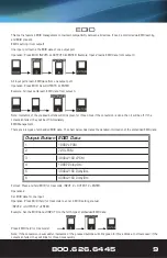
Page 9: ...onversion failed they will be off immediately EDID Management There are six types of embedded EDID data The chart below illustrates the detailed information of the embedded EDID data Output Button EDID Data 1 1080P LPCM 2 720 LPCM 3 3840x2160 LPCM 4 1080P Dolby Dts 5 3840x2160 Dolby Dts 6 4096x2160 Dolby Dts Format Press and hold EDID for 3 seconds INPUT OUTPUT ENTER Operations Set EDID data for o...

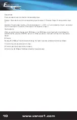
Page 10: ...nds Then output 2 corresponds to input 1 Clear operation When you switch output channel learn EDID data or set EDID data press Clear button to withdraw the operation before you press ENTER to carry it on When you press it the matrix will return to the previous status IR Control By using IR HDBaseT transmission technology the matrix has some additional functions as follows 1 Control far end output ...

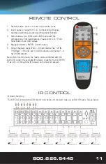
Page 11: ...ontrol for details 4 Navigation buttons ENTER Confirm button 5 Output channels range from 1 8 Each channel has 1 IR IN 1 HDBaseT 1 RS232 and 1 AUDIO outputs and channel 1 4 have HDMI outputs Note With this IR remote the matrix can be controlled with the built in IR sensor the extended IR receiver connected to the IR EYE IR ALL IN or through the IR receiver on the far end receiver IR Matrix Switchi...

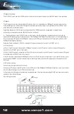
Page 12: ...r of 4K HDBaseT 8x8 Matrix Switcher Example Send command 3R2 II to transfer IR signal received from zone 2 to IR OUT port 3 2 Force Carrier a Only if the IR receiver connected to HDBaseT receiver is with IR carrier can the received IR signal be transferred to IR OUT port of the matrix b Only if the IR receiver connected to IR ALL IN port of the matrix is with IR carrier can the received IR signal ...

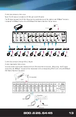
Page 13: ...ransmitted to the corresponding IR OUT port of the 4K HDBaseT 8x8 Matrix Switcher See below Receiver 1 Receiver 2 Receiver 3 Receiver 4 Receiver 5 Receiver 6 Receiver 7 Receiver 8 HDMI OUT HDBT IN Tx Rx RS232 IR IN IR OUT PoC HDMI OUT HDBT IN Tx Rx RS232 IR IN IR OUT PoC HDMI OUT HDBT IN Tx Rx RS232 IR IN IR OUT PoC HDMI OUT HDBT IN Tx Rx RS232 IR IN IR OUT PoC HDMI OUT HDBT IN Tx Rx RS232 IR IN I...

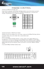
Page 14: ...32 Control Software Installation Copy the control software file to the computer connected with 4K HDBaseT 8x8 Matrix Switcher Uninstallation Delete all the control software files in corresponding file path RS232 Control Modes To control the 4K HDBaseT 8x8 Matrix Switcher you need to connect its 9 pin female RS232 port to a PC s RS232 port or you can just connect any one of the HDBaseT receiver s R...

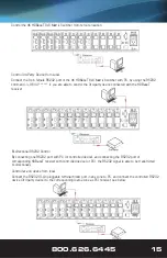
Page 15: ...d with the HDBaseT receiver Bi directional RS232 Control By connecting one RS232 port with PC or controlled device and connecting the RS232 port of corresponding HDBaseT receiver with controlled device or PC the RS232 signal is able to be transmitted bi directionally Control far end device from local Connect the RS232 3 pin pluggable terminal block port in any zone to PC and connect the controlled...

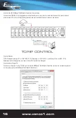
Page 16: ...ame zone as controlled device receiver see below TCP IP CONTROL Control Modes TCP IP default settings IP is 192 168 0 178 Gateway is 192 168 0 1 and Serial Port is 4001 IP Gateway can be changed as you need Serial Port cannot be changed Controlled by Single PC Connect a computer to the TCP IP port of the 4K HDBaseT 8x8 Matrix Switcher and set its network segment to the same as the 4K HDBaseT 8x8 M...

Page 17: ...rk segment to the same as the router Step4 Set the PC s network segment to the original ones Step5 Connect the 4K HDBaseT 8x8 Matrix Switcher and PC s to the router PC s within the LAN is able to control the 4K HDBaseT 8x8 Matrix Switcher asynchronously Then it s able to control the device via GUI GUI for TCP IP control 4K HDBaseT 8x8 Matrix Switcher provides with built in GUI for convenient TCP I...

Page 18: ...carry on the connections by clicking corresponding button Buttons 1 9 at the right bottom corner provides quick saving and recall for overall connection status Users Display or modify credential settings front panel lock and GUI version If there is any modification press Save to restore the settings or press Cancel to withdraw Interface Set title bar label LCD readout and button labels press Save ...

Page 19: ...every input and manage EDID See the screenshot below Note with HDCP compliant sources HDCP NEEDS TO BE SET TO ON Network Inquire and configure network settings including MAC address IP address subnet mask and Gateway Note Log in as user access main interface only ...

Page 20: ... IR remote CAUSE The IR receiver connected to IR IN IR ALL IN port is not with carrier SOLUTION Change for an IR receiver with carrier 10 PROBLEM Power Indicator remains off when powered on CAUSE Failure in power connection SOLUTION Check whether the cables are connected correctly 11 PROBLEM EDID management does not work normally CAUSE The HDMI cable is broken at the output end SOLUTION Change for...

Page 21: ...Most of the major source and display manufacturers employ a proprietary control channel to communicate between devices from the same manufacturer Sometimes this can interfere with the HDMI control circuit or the authentication of the signal Call the manufacturer if you experience this issue Sometimes a player an audio video receiver or a cable satellite box may not have the latest software update ...

Page 22: ...nical Support by dialing 1 800 626 6445 You can also email technical support issues to techsupport vanco1 com When calling please have the Model Number Serial Number affixed to the bottom of the unit and Invoice available for reference during the call Please read this Instruction Manual prior to calling or installing this unit since it will familiarize you with the capabilities of this product and...

Page 23: ...vice pursuant to part 15 of the FCC Rules These limits are designed to provide reasonable protection against harmful interference in a commercial installation Operation of this equipment in a residential area is likely to cause interference in which case the user at their own expense will be required to take whatever measures may be necessary to correct the interference Any changes or modification...

Page 24: ...Vanco International 506 Kingsland Drive Batavia Illinois 60510 call 800 626 6445 fax 630 879 9189 visit www vanco1 com ...

Reviews: