background image

www.vanco1.com

800.626.6445

10

IR RECEIVER (RX)

• 

To control the source: Plug IR Receiver into IR RX port of receiver unit (EVEXFBR1-RX); place receiver at 
or near display

• 

To control the display: Plug IR Receiver into IR RX port of transmitter unit (EVEXFBR1-TX); place receiver 
in position where it is able to receive remote signals

Summary of Contents for EVEXFBR1

Page 1: ...Vanco Part Number EVEXFBR1 HDMI Extender over Fiber with IR and RS 232 www vanco1 com 800 626 6445 HDMI E X TE N DER over Fiber with IR and RS 232 ...

Page 2: ...cularly at the plugs 9 Use unit only with accessories specified by the manufacturer 10 Refer all servicing to qualified personnel CAUTION HDMI is a very complex technology requiring continuous authentication of the signal and the same video resolution and audio settings on all electronic equipment in the system When there are multiple sources and displays the video resolution and audio setting on ...

Page 3: ...l signals and carries the signals via fiber optic cables The receiving unit is responsible for equalizing the transmitted HDMI signal and reconstructing IR signals Both units require power FEATURES Transmits audio and video via HDMI as well as bi directional IR and RS 232 Transmission range 984ft 300m over multi mode fiber optic cables 6 2mi 10km over single mode fiber optic cables Supports 4K 60H...

Page 4: ...olts peak to peak TTL ESD Protection Human body model 15kV air gap discharge 8kV contact discharge PCB Stack up 4 layer board impedance control differential 100Ω single 50Ω IR Pass thru Bi directional RS 232 Support Yes HDMI Source Control Controllable via IR pass through from RX to TX with IR extenders HDMI Connector Type A 19 pin female 3 5mm Connector IR receiver IR blaster Operation Temperatur...

Page 5: ...hts Both LEDs should be illuminated for proper functionality link indicates that both the TX and RX are communicating 5 SFP OUT Connect fiber optical cables from this unit to the RX multimode modules included 6 HDMI IN Connect an HDMI source 7 IR IN Connect the included IR Receiver RX to control the display 8 IR OUT Connect the included IR Transmitter TX to control the source 9 DC 12V Connect the ...

Page 6: ...e Control Type Setup section 4 Power and Link Lights Both LEDs should be illuminated for proper functionality link indicates that both the TX and RX are communicating 5 SFP IN Connect multimode fiber optical cables from this unit to the TX multimode modules included 6 HDMI OUT Connect an HDMI display 7 IR IN Connect the included IR Receiver RX to control the source 8 IR OUT Connect the included IR...

Page 7: ...N 2 and 3 The dip switches allow for firmware updates and to either activate or de activate IR as well PIN 1 See below for dip switch settings note that DOWN is ON and both TX and RX need to be set to the same dip switch settings DIP Switch Position Description TX RX PIN 1 ON For system firmware update OFF Default and normal setting PIN 2 ON Reserved for future use OFF RS 232 IR function ON PIN 3 ...

Page 8: ... when either unit is plugged in At this point the display connected should display the source signal connected to the extender set If no signal is being displayed connect a fiber optical cable to rule out cabling If a display is having difficulty receiving a signal access the display s menu and adjust the resolution lowest to highest until signal is displayed A 24 Hz vertical refresh rate may work...

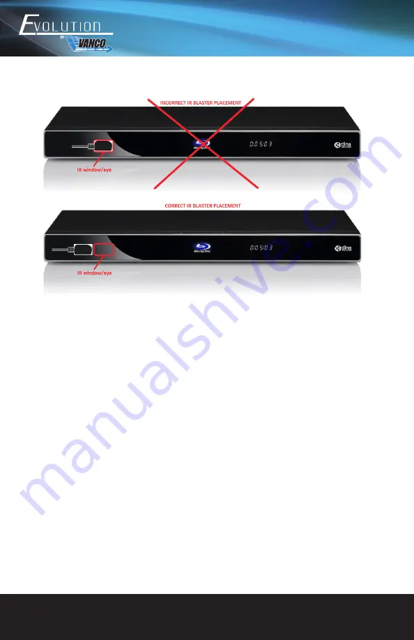
Page 9: ...e 3 Use only the IR accessories that are included with this extender using third party IR blasters and or receivers may not work IR Receiver IR Blaster IR Blaster TX To control the source Plug IR Blaster into IR TX port of transmitter unit EVEXFBR1 TX place blaster in front of the IR eye of the source To control the display Plug IR Blaster into IR TX port of receiver unit EVEXFBR1 RX place blaster...

Page 10: ...e Plug IR Receiver into IR RX port of receiver unit EVEXFBR1 RX place receiver at or near display To control the display Plug IR Receiver into IR RX port of transmitter unit EVEXFBR1 TX place receiver in position where it is able to receive remote signals ...

Page 11: ...he IR Receiver into the IR RX Port on the Receiver place receiver at or near display To Control the Display 1 Plug the IR Receiver into the IR Receiver Port on the Transmitter place receiver in position where it is able to receive remote signals 2 Plug the IR Blaster into the IR Blaster port on the Receiver place transmitter in front of the IR eye of the display ...

Page 12: ...ype of HDMI sources and the type of HDMI display 4 Ensure proper termination of the fiber optical cables and if the cables are joined at some point that it has been properly completed 5 The quality of fiber optical cables can have a major effect on how long the transmission limit can achieve and quality of picture the actual transmission range is subject to the Cat5e 6 cable utilized For the best ...

Page 13: ... the hot plug concept With all of the HDMI cables disconnected turn on the source and plug in the HDMI cable into it s output then power up the Vanco unit and plug the HDMI cable into it s input finally turn on the display and plug the HDMI cable from the receiver into it This activates all of the devices in corresponding order and results in a signal being plugged into a device that is on and wil...

Page 14: ...ector power conditioner unit or an uninterruptible power supply must be installed in the electrical circuit to protect against power surges If repairs are needed during the warranty period the purchaser will be required to provide a sales receipt sales invoice or other acceptable proof of purchase to the seller of this equipment The seller will then contact Vanco regarding warranty repair or repla...

Page 15: ...ns For additional information such as helpful installation videos etc please visit www vanco1 com LIABILITY STATEMENT Every effort has been made to ensure that this product is free of defects The manufacturer of this product cannot be held liable for the use of this hardware or any direct or indirect consequential damages arising from its use It is the responsibility of the user and installer of t...

Page 16: ...Vanco International 506 Kingsland Drive Batavia Illinois 60510 call 800 626 6445 fax 630 879 9189 visit www vanco1 com ...

Reviews: