


RELIANT RS45 AIR COMPRESSOR
SECTION 4: OPERATION
090126-OP_r0 (JAN-2018)
PAGE - 19
VANAIR MANUFACTURING, INC.
(844) VAN-SERV • www.vanair.com
4.3 NORMAL OPERATION
Following is an overview of the normal
operation of the Vanair RS45 hydraulic
compressor system from start-up to shut-
down. This overview of a typical sequence of
events may not cover all situations.
4.3.1 INITIAL START-UP PROCEDURE:
PRE-CHECKS
Following are step-by-step instructions for
the initial start-up of the RS45 hydraulic
compressor system:
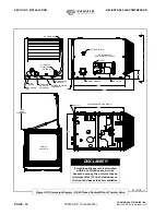
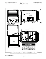
1. Ensure the compressor is positioned on a
level surface so that the proper amounts
of oil can be added, if required.
2. Unit should be bolted down.
3. Ensure all hose connections are tight and
wiring connections correct and tight.
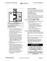
4. Check compressor oil level
(refer to
Figures 4-2
and
4-3
)
.
Add or drain if necessary to accomplish the
recommended compressor oil level.
5. Ensure hydraulic oil to pump inlet, and
prime if necessary.
6. Ensure service valve on compressor is
closed.
7. Engage hydraulic system (PTO or
hydraulic supply) and allow hydraulic oil
to circulate back to tank. When solenoid
is activated, oil should quickly circulate to
the hydraulic motor on the compressor,
and start producing air.
8. Check for leaks.
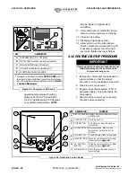
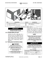
9. Refer to
Figure 4-5
. Press the START
button on the Controller, and wait for
the Main Screen (default is the
Pressure Screen). Check pressure and
temperature screens. Pressure may
need adjustment to achieve desired
operating pressure. Refer to
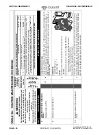
Section
5, Table 5A: Routine Maintenance
Schedule
.
10. Partly open service valve to load
compressor and allow to warm up.
Monitor temperature; The ideal
IMPORTANT
If start-up and shut-down procedures are
not followed, damage to the system and its
components may occur.
WARNING
Do not rely on hoses to hold the module in
position.
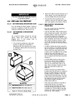
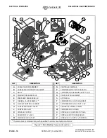
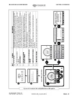
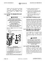
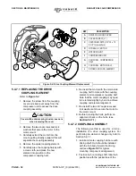
KEY
DESCRIPTION
A
RED COMPRESSOR FILL CAP
B
FILL CAP BLEED VENT GROOVE
C
Open/crack cap
slightly
to allow bleed
vent to relieve pressure
Figure 4-2: Pressure Relief
A
B
C
NOTE
An alternate compressor oil level check can
be accomplished via the compressor sight
glass. Refer to Table 5A, Key #1, in Section
5, Maintenance for details.
WARNING
DO NOT remove caps, plugs and/or other
components when compressor is running
or pressurized. Stop compressor and de-
pressurize system prior to maintenance of
system. Relieve the entire system pressure
by opening the service valve, which will
vent all pressure to the atmosphere.
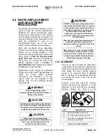
Wear personal protective equipment such
as gloves, work boots, and eye and
hearing protection as required for the task
at hand.
Summary of Contents for Reliant RS45
Page 86: ...BLANK PAGE...
Page 87: ...BLANK PAGE...


