5000/10000 FLYWHEEL GRINDER
MACHINE MAINTENANCE
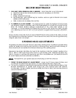
1.
COOLANT TANK REMOVAL AND CLEANING:
Clean Tank after every 50 flywheels
a. Open front access door and pull entire coolant unit completely out onto floor.
b. Remove pump.
c. Empty, clean and flush tank.
d. Re-install pump, slide unit half way into machine, add one quart of 794-8011-40 coolant
additive and fill with water.
e. Slide coolant unit completely into machine.
2.
FLYWHEEL E-Z LOCK INSERT:
The table spindle into which the flywheel hold down bolts
get threaded contains a threaded insert. This replaceable E-Z Lok insert is provided so that
when the threads become damaged replacement of the entire table spindle is not
necessary. It is recommended that replacement should be done before the insert's threads
are completely worn out. An E-Z Lok insert extractor is supplied with the grinder (794-8637-
45)
Once a month, remove the E-Z Lok insert (794-8017-44) from the center of the table, and coat
the threads with an anti-seize lubricant. This will prevent the insert from becoming permanently
lodged in place from rust and grit.
GRINDING HEAD ADJUSTMENTS
All grinding should be done with the rear edge of the grinding wheel. Insufficient rearward tilt as
evident by sparks from both the front and rear of the wheel may result in abnormal heating of
the work piece and necessitate more frequent dressing of the grinding wheel.
Experience has shown that tilting the head of the machine so that the indicator reading at the
rear is .020” to .025" lower than at the front is a good starting point. Individual operators may
want to increase or decrease tilt depending upon their own preferences. (Increased tilt should
be used if higher stock removal rates are desired.)
NOTE:
The head tilt on your grinder was set at the factory at .023” tilt to the rear.
1.
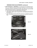
FRONT TO REAR HEAD TILT ADJUSTMENT:
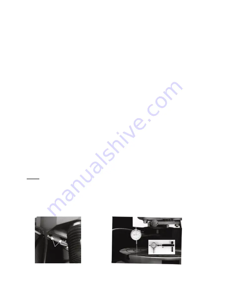
Loosen two 7/16 cap screws (5/8 Hex) and
turn the pair of socket head cap screws in or out to obtain desired tilt, (Figure 29).
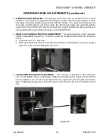
2. Tilt may be checked by attaching the Optional Dial Indicator and Mounting Hardware, Part
Number 794-8685-32, to grinder motor (Figure 30), and lowering head until indicator
touches table. Rotate indicator (and motor shaft) from front to back and note direction and
amount of indicator travel.
Figure 29
Figure 30 Optional – Part # 794-8627-83
Van Norman
33.
888-855-1789
Summary of Contents for FG5000
Page 2: ......
Page 4: ......
Page 11: ...5000 10000 FLYWHEEL GRINDER STANDARD EQUIPMENT FG5000 FG10 000 Van Norman 7 888 855 1789...
Page 21: ...5000 10000 FLYWHEEL GRINDER MACHINE DESCRIPTION Van Norman 17 888 855 1789...
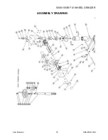
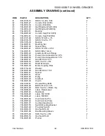
Page 41: ...5000 10000 FLYWHEEL GRINDER ASSEMBLY DRAWING Van Norman 37 888 855 1789...
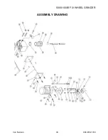
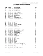
Page 42: ...5000 10000 FLYWHEEL GRINDER ASSEMBLY DRAWING Van Norman 38 888 855 1789...
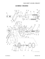
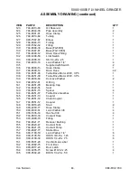
Page 43: ...5000 10000 FLYWHEEL GRINDER ASSEMBLY DRAWING Van Norman 39 888 855 1789...
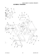
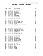
Page 44: ...5000 10000 FLYWHEEL GRINDER ASSEMBLY DRAWING Van Norman 40 888 855 1789...
Page 81: ......

