


© July 2017 Van Essen Instruments. All rights reserved
.
2
1.2
System Overview
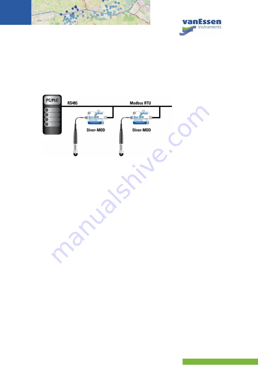
A typical Modbus configuration is depicted in Figure 2. In the schematic two Diver-MODs are
connected to a PC/PLC. This connection includes both data communication and power. The
maximum Modbus cable length depends on the baud rate, the cable (gauge, capacitance or
characteristic impedance), the number of loads on the daisy chain, and the network configuration
(2-wire or 4-wire). For a maximum baud rate of 9600 and AWG26 or wider gauge, the maximum
length is 1000 meters.
Figure 2
example Modbus network with PC/PLC and 2 Diver-MODs.
Each Diver-MOD is connected to a Diver through a Diver communication cable. The maximum length
of the Diver communication cable is 500 meters.
Each Diver-MOD must be programmed with a unique address (0 to 247). Messages sent to the
address 0 will be accepted by all Diver-MODs. The Diver-MOD acts as a slave for the PLC/PC that
requests the data from each Diver-MOD.
Up to 8 Diver-MODs can be used per Modbus network. The Diver-MOD is powered by the Modbus
network. Each Diver-MOD is equipped with a 120 (1/4 W) termination resistor that can be used by
applying the termination jumper.
The Diver-MOD is in accordance with the
Modbus Application Protocol Specification V1.1b3
and
enables to interface Divers in a RS485 network using the Modbus/RTU protocol. The Modbus TCP/IP
is not supported.
2
Getting Started
2.1
Supported Equipment
The Diver-MOD can be connected to a Diver via a Diver Cable AS2xxx using the M12 connector. The
following Divers can be used with the Diver-MOD:
TD and Baro-Diver (model DI8xx),
Mini and Baro-Diver (model DI5xx),
Micro-Diver (model DI6xx),
Cera-Diver (model DI7xx), and
CTD-Diver (model DI27x).
Detailed information about supported equipment can be found in Appendix D.