background image

INSTRUCTIONS MANUAL 

AIRBRUSH MANUAL EXTERNAL MIX EQUIPMENT


13


10. After that press the 

gun trigger (18)

 and fill the measuring cylinders up to the 

desired quantity.  

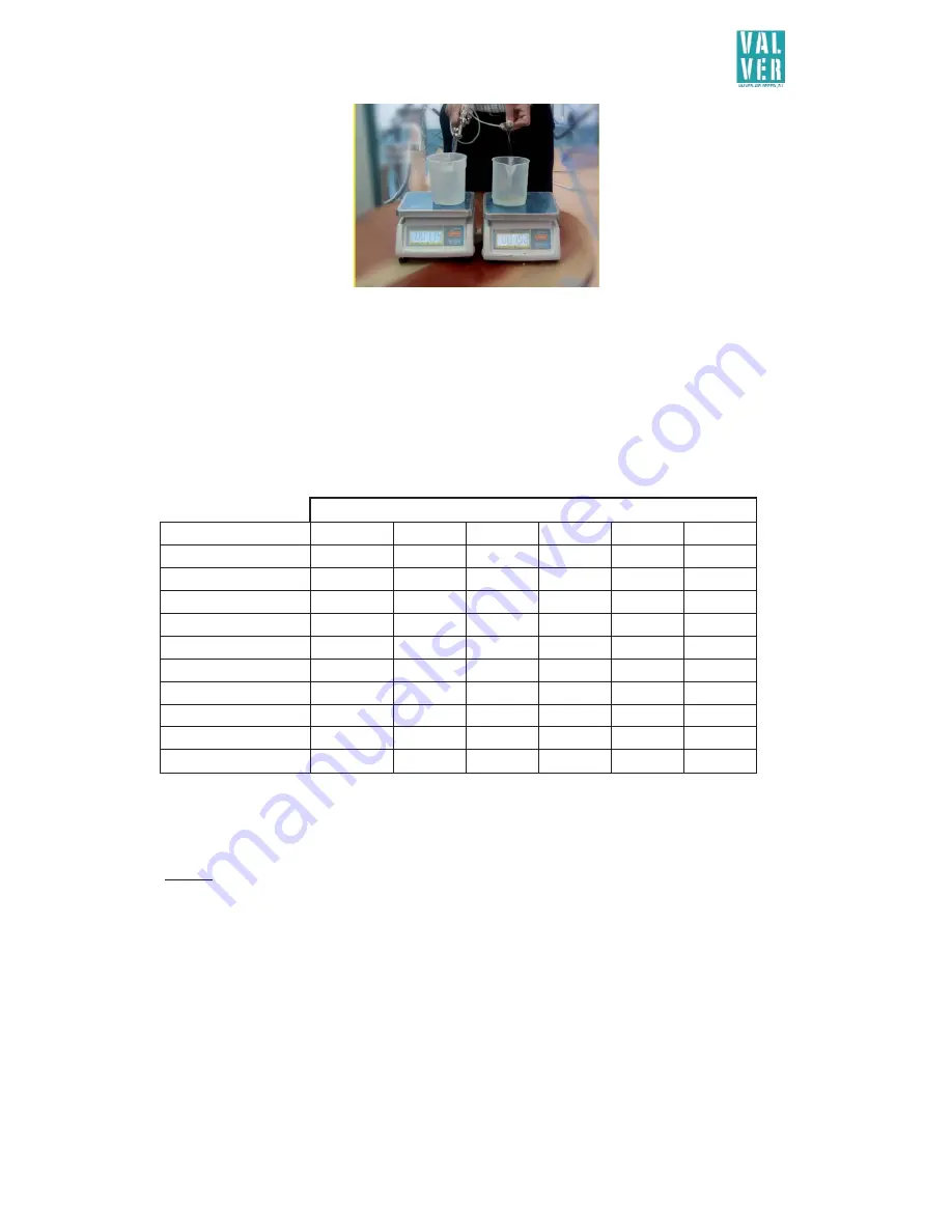
11. Check the volume proportion or the material weight with a balance and adjust 

the proportion with the 

catalyser pump air control (10) 

at the pressure tank or 

with the 

catalyser regulator (24)

 of the pistol. In case of two-component-

products application with a small mix ratio the machine is equipped with a 

micrometric valve (21).

 To adjust the mixture proportions directly with the 

micrometric valve, please follow the guidance table and the advices: 

PRESSUREINLETPRESSURETANK

VALVEROTATIONS

 0,5

0,6

0,7

0,8

0,9

1

1

0

0

0

0

0

0

2

2,1

2,6

3,4

3,7

4,7

5,2

3

5,4

6,2

7,3

8,1

9,1

10

4

8,2

9,9

11,3

12,9

14,3

15,6

5

12,1

13,5

15,4

15,9

17,1

17,8

6

16,4

18,6

21,9

23,1

25,4

26,7

7

20,8

24,8

28,7

30,4

32

33,2

8

25,7

30,2

34

36,6

39,2

42,4

9

33,6

40,2

44,7

46,9

50,1

53,8

10

48,7

54,4

59,7

64,2

69,6

72,6


This table facilitates and orientates only for the start-up procedure. Attention! It is neither an 
orientation nor an exact formula, because these flows always may vary depending on viscosities, hose 
length and material losses.  


Advices: After finishing step 6 and achieving the required quantity of 

component A

 it will be 

proceeded to the final calibration of the catalyst or 

component B.


Therefore the flow per minute of the component A has to be controlled by a balance removing the 
spray air from the pistol.  

When we know the resin flow per minute selected by the user, for example 150g/min, we 

have to multiply this with the catalyst or component B mix percentage expressed by the application 
product manufacturer, for example 5% means 150 x 0.05 = 8g/min. Looking to the table we have two 
consistent adjustment options. 

Option 1

. Feeding the pressure tank with the 

catalyser air pump control (10

) with 0.5 bar and 

turning the knob of the 

micrometric valve (21)

 4 times starting at 0  

Opción 2

. . Feeding the pressure tank with the 

catalyser air pump control (10

) with 0.8 bar and 

turning the knob of the 

micrometric valve (21)

 3 times starting at 0  

               If  we  aim  for  option  2  we  get  the  more  balanced  valve  regulation  option,  where  the  catalyst 
pressure is closer to the resin pressure.  

Summary of Contents for AIRBRUSH MANUAL EXTERNAL MIX EQUIPMENT

Page 1: ......

Page 2: ...RT HANDLING AND STORAGE 9 3 OPERATION 9 3 1 Safety rules 9 3 2 Starting up the equipment 10 3 3 Calibration 12 4 MAINTENANCE AND CLEANING 15 5 SAFETY RULES 16 6 DISASSEMBLY CONDITIONS 16 MANUAL EXTERN...

Page 3: ...s in the market obtaining the catalyst or component B mixture and integration together with the resin or component A Thanks to a careful and studied design with compressed air sprayer at both ends of...

Page 4: ...ount in its the design and manufacture x UNE EN ISO 12100 2012 Safety of machinery General principles for design Risk assessment and risk reduction x UNE EN ISO 4414 2011 Pneumodrives General rules an...

Page 5: ...smantling of the machinery If it is absolutely necessary to send Valver Air Speed S L staff out it will always be done at their own discretion and an invoice will be issued for the job plus the travel...

Page 6: ...tank A specially prepared spray gun for combining and applying the two products The two products are always separated prior to their reaching the gun tip where they are then mixed by the air fan This...

Page 7: ...gulator Resin regulator 10 DOUBLE DIAPHRAGM option for 2 or 4 spray guns Option for 2 guns Can incorporate sets of 2 8 18 L pressure tanks and combined with a double diaphragm pump 4 1 12 7 8 resin ca...

Page 8: ...hragm for resin pressure tank 2 L for catalyst 4 1 5 6 7 8 resin 10 DOUBLE DIAPHRAGM for RESIN PRESSURE TANK for CATALYST option 2 14 13 12 11 9 8 9 1 4 Resin regulator 21 2 resin catalyst 3 5 10 L RE...

Page 9: ...0 Catalyser pump air control 11 Catalyser pump bleed 12 Catalyser valve 13 Intake air mixer adaptor 14 Mixer air stopcock 15 Gun 16 Catalyser head tube 17 TRIMIX mixer head 18 Gun trigger 19 Gun tip 2...

Page 10: ...quipment To avoid breaking pressure hoses or items to check before the equipment implementation x All components are not worn or damaged x Fittings and joints of the filters are very tight x Use the m...

Page 11: ...air gun control 7 7 Set the air gun control 7 to 0 bar to avoid splashing 8 Open the resin valve 5 and adjust the resin pump air control 4 9 Place the gun tip 19 in the nozzle of the resin test tube u...

Page 12: ...ns Clean the AIRBRUSH MANUAL EXTERNAL MIX EQUIPMENT thoroughly after use Proper maintenance will extend the equipment s useful life Always use the solvent recommended by the product s manufacturer for...

Page 13: ...ne by opening the material needle regulator 23 until adjusting the desired product output This can also be adjusted by changing the flow of the available needles 0 8 1 0 1 3 1 5 1 8 2 0 and as well by...

Page 14: ...start up procedure Attention It is neither an orientation nor an exact formula because these flows always may vary depending on viscosities hose length and material losses Advices After finishing ste...

Page 15: ...22 Adjust the spray pressure according to the nature of the product and user requirements with the air gun control 7 16 Adjust the pressure with the air gun control 7 or with the spread regulator The...

Page 16: ...requently when in use 2 Always leave the TRIMIX mixer head 17 immersed in cleaning solvent When left unused for long periods place in a tightly sealed recipient with solvent This will impede the evapo...

Page 17: ...verifying the correct operation of the equipment and the early detection of possible problems We recommend that such revisions be carried out at least once a week Preventive maintenance every 7 days C...

Page 18: ...Solvent based Water based Resin Type polyurethane acrylic polyester gel coat etc A Component Reference Viscosity Formula for TOTAL Formula for RESIN Resin Accelerator Diluent Other B Component Referen...

Page 19: ...midity BEFORE CALIBRATING AFTER CALIBRATING TEXT n Threads nozlle Regulator gun needle laps Resin pump pressure Catalyst pump pressure Dose catalyst g ml Dose resin g ml catalyst resin 1 2 3 4 5 6 7 8...

Page 20: ...ns Weight part without appling g Weight part freshly applied g Weight part at 30 min g Weight part at 60 min g Drying To contact min In package min TEXT 6 Piece dimensions Weight part without appling...

Page 21: ...30 28 26 24 23 21 20 19 18 17 17 16 15 58 51 47 43 40 36 33 31 29 27 25 23 21 20 20 19 18 17 16 16 61 55 50 46 42 38 35 32 30 28 26 24 22 21 20 19 18 17 16 16 69 63 56 52 46 42 39 35 32 30 28 25 24 23...

Page 22: ...INSTRUCTIONS MANUAL AIRBRUSH MANUAL EXTERNAL MIX EQUIPMENT 21 APPLICATION GUN EXPLODED...

Page 23: ...INSTRUCTIONS MANUAL AIRBRUSH MANUAL EXTERNAL MIX EQUIPMENT 22...

Page 24: ...INSTRUCTIONS MANUAL AIRBRUSH MANUAL EXTERNAL MIX EQUIPMENT 23...

Page 25: ...INSTRUCTIONS MANUAL AIRBRUSH MANUAL EXTERNAL MIX EQUIPMENT 24...

Page 26: ...INSTRUCTIONS MANUAL AIRBRUSH MANUAL EXTERNAL MIX EQUIPMENT 25 MAINTENANCE OPERATIONS OPERATION PERIODICITY maintenance personal DAILY WEEKLY MONTHLY SEMIANNUAL INDICATE THE DATE...

Reviews: