Valtra 95 Service Manual Download Page 15

13

Model

Code

Page

12. Repairs

1. 11. 2000

120

3

95, 105, 115

X100-X120

É

É

ÇÇÇÇ

ÇÇÇÇ

ÉÉÉÉ

ÉÉÉÉ

ÉÉÉÉ

4

5

3

2

1

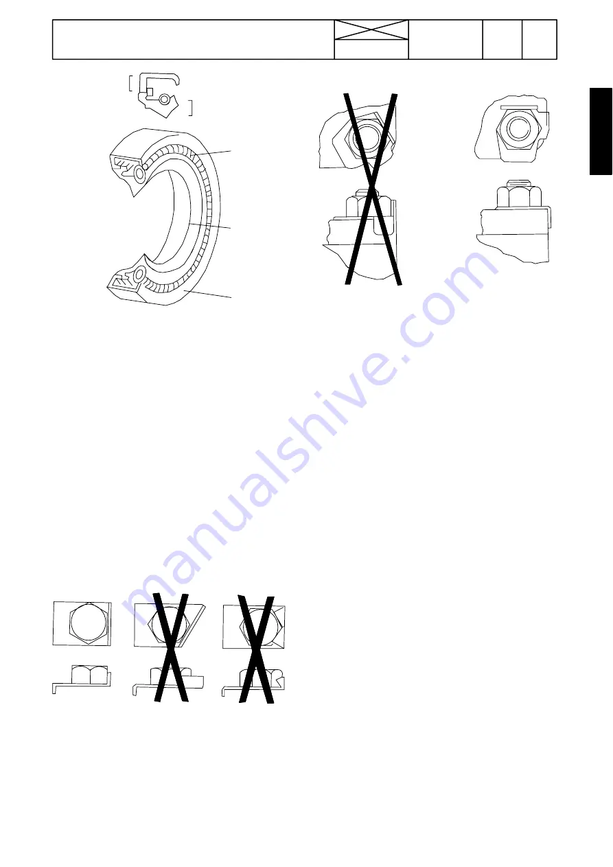
The main parts of lip-type seal:

1. Case

2. Sealing element

3. Ring spring

The figure above shows the construction of a  simple lip-type

seal. The cross section shows the heel (4) and the toe (5),

used to identify the sides of a single element seal. With a few

exceptions, the toe of a single-lip is located on the lubricant

side. Some seals have a second auxiliary lip which has no

spring.

Cables and wires

When removing or disconnecting a group of cables or wires,

label each one to ensure correct refitment.

Locking  devices

Correct and incorrect use of retainers

Correct and incorrect method of fitting and bending locking

tabs.

Slackening  of  nuts  and bolts is prevented by mechanical

means such as lockwashers, tab washers and cotter pins, or

by Loctite-type locking agents.

Flat retainers must be installed properly to be effective. Bend

one end of the retainer against the edge of the  part. Bend the

other end against one of the nut or bolt head.Always fit new

retainers in compartments which house moving parts. When

fitting lockwashers  on  aluminium  housings,    place  a  flat

washer between the lockwasher and the housing.

Note!

1) Never fit a lockwasher (Grower, fan, spring, etc.) under a nut

or bolt to which a specified torque has to be applied.

2) Always thoroughly degrease components before applying

Loctite type locking agents.

Bushes and press fits

Do not fit bushes with a hammer alone. Use a suitable  fitting

tool and a hammer or, better still, a press if possible..

When using a press, ensure that pressure is applied directly

in line with the bore. If the ring has an oil hole, take care to align

it with the oil hole in the mating part. When press fitting a part

into another part, lubricate the mating surfaces. Tapered parts

should be assembled dry. Before assembly, check that the

tapers are dry and free from burrs.

Fitting bolts in blind holes

Use bolts of the correct length. A bolt which is too long may

"bottom" before the head comes into contact with the part it

is to hold: this will cause damage to the threads. If a bolt is too

short, there may not be enough threads engaged to hold the

part securely.

Summary of Contents for 95

Page 1: ...e Electrical system Valtra Inc SF 44200 Suolahti Finland Power transmission Brake system Steering sys tem and Front axle Frame and Wheels Tools Cab and Shields Hydraulics 10 20 30 95 105 115 X100 X110...

Page 2: ...Order no 39 214 211 ENGLISH Find manuals at https best manuals com...

Page 3: ...10 General 11 Layout 12 Repairs 13 Maintenance Find manuals at https best manuals com...

Page 4: ...2 Find manuals at https best manuals com...

Page 5: ...he machine Certain operations should be carried out with the aid of special tools designed by Valmet Valmet Tractors Inc Tractor Service IMPORTANT ValtraValmet 95 105 and 115 tractors are based on Val...

Page 6: ...4 Find manuals at https best manuals com...

Page 7: ...4 5 2004 The following supplements have been published for the Valtra X100 X120 Service Manual Ordering number Date Notes 39 261 211 24 5 2004 Supplement no 39 261 211 24 5 2004 Includes Agroline inst...

Page 8: ...6 Find manuals at https best manuals com...

Page 9: ...ission a s o The number designation for each group is given in the top left box of the respective pages and the first figure in the code designa tion 410 1 50 60 70 80 90 100 Code Page 2 Division into...

Page 10: ...ssue is printed in the crossed over box and the date of the current issue is printed in the real date box 6 Model At the top of each page the tractor model for which the page is valid is indicated 7 A...

Page 11: ...wiring diagrams 314 Autocontrol 2 2 2 3 321 ACB power lift 330 Agrodata on board computer 331 AD instrument 370 Autocontrol 5 5 2 HiTech 371 Autocontrol 5 2 40 Power transmission 41 Clutch fluid coupl...

Page 12: ...data tools description 641 Front axle housing 643 Hubs 644 Differential 645 Adjustments 70 Frame and wheels 710 Tractor frame 720 Tyres and wheel discs 80 Cab and shields 810 Cab 820 Shields 830 Air c...

Page 13: ...n order of dimension quality and surface treatment The values given in the table should be used if the tightening torque is not given in the repair instructions Safety Always bear safety in mind when...

Page 14: ...nection and the surrounding area As soon as a line has been disconnected cap plug or tape the line or opening to prevent the ingress of foreign ma terial The same cleaning and covering precautions sho...

Page 15: ...st one of the nut or bolt head Always fit new retainers in compartments which house moving parts When fitting lockwashers on aluminium housings place a flat washer between the lockwasher and the housi...

Page 16: ...5 M10 50 5 45 5 60 5 70 7 90 10 M12 90 10 80 8 100 10 125 10 151 15 M14 140 15 125 10 160 15 200 20 240 20 M16 220 20 195 20 250 25 300 30 370 40 M18 300 30 270 30 350 35 430 40 510 50 M20 430 40 380...

Page 17: ...hp 0 746 kW the point at which the measurement was taken kilowatts kW Engine torque newton metres Nm 1 Nm 0 74 ft lb 1 ft lb 1 356 Nm Fuel consumption by weight kilograms per hr kg h 1 kg h 2 2 lb hr...

Page 18: ...16...

Page 19: ...s when changing Large amounts of dirt e g heavily clogged filters can point to a fault which could cause extensive and costly repairs if not corrected in time When carrying out checks the tractor shou...

Page 20: ...xle only frame steering bearings 2 nipples steering cylinders bearings 4 nipples 7 Check oil level in transmission and hydraulics 8 Clean the prefilter of the engine air intake 9 Check belt belts tigh...

Page 21: ...on strainer 23 Change oil in front axle differential and hubs 24 Change cab ventilation air filter and recirculation filter 25 Change fuel filter and change pre filter X100 X120 26 Change air filter a...

Page 22: ...water anti freeze agent standard ASTM D3306 86a or BS 6580 1985 20 5 X100 6580 1985 17 X110 X120 22 Brake fluid reservoir Brake fluid SAE J1703 0 3 Clutch fluid reservoir not HiTech Brake fluid SAE J...

Page 23: ...3 Check hydraulic oil level Maintenance at every 250 hours 4 Grease the drive shaft of the loader s variable displace ment pump 3 nipples Maintenance at every 1000 hours or yearly 5 Change hydraulic o...

Page 24: ...22...

Page 25: ...20 Engine 21 Engine 22 Fuel system 23 Cooling system 21...

Page 26: ...22...

Page 27: ...C Changing flywheel starter gear 7 D Fitting flywheel 7 Cylinder head and valve mechanism Op no 212 1 Cylinder head A Removing cylinder head 1 B Removing valves 1 C Checking cylinder head 1 D Changin...

Page 28: ...ving timing gear casing 1 B Reconditioning idler gear 1 C Fitting timing gear casing 2 Lubrication system and oil sump Op no 215 A Reconditioning oil relief valve for lubrication oil pressure 1 B Remo...

Page 29: ...m r min DIN 430 1400 460 1400 490 1400 Moment rise 35 31 28 Low idling r min 850 850 850 Compr press 1 bar 24 24 24 Max no load revs r min 2400 2400 2400 1 Minimum value at operating temperature and s...

Page 30: ...iameter of camshaft bearing bores others than no 1 50 000 50 025 mm Camshaft clearance in bearing bush no 1 0 060 0 145 mm Camshaft clearance in bearing bushes others than no 1 0 090 0 140 mm Camshaft...

Page 31: ...rod 40 025 40 040 mm Outside diameter of piston pin bush 44 082 44 120 mm Interference fit connecting rod small end bushing connecting rod 0 057 0 120 mm Connecting rod small end bore 44 000 44 025 Co...

Page 32: ...verthick thrust plate 45 300 45 380 mm 4th oversize two 0 2 mm overthick thrust plates 45 400 45 480 mm Other crankshaft journals may not be ground longer Crankshaft end float 0 100 0 380 mm Max permi...

Page 33: ...173 7 742 8 331 8 939 9 567 10 213 Cylinder head Height of cylinder head 104 800 105 000 mm Height min of cylinder head after repair grinding 104 000 mm Cylinder head straigthness in lateral direction...

Page 34: ...ngs crankshaft gear lubricating oil pump gear 0 05 0 25 mm between the pump gears 0 16 0 26 mm Diameter of drive shafts at bearings for body and cover 17 966 17 984 mm at gear wheel pressed on shaft 1...

Page 35: ...using attaching bolts 22 Nm Nut at end of shaft 8 1 Nm By pass passage opening pressure S1BG 1 035 bar 1 Measured at nut on end of shaft Tightening torques Main bearing bolts 200 Nm Cylinder head bolt...

Page 36: ...101 75800 Milling cutter for facing inlet valve seat 16 9101 65505 Milling cutter for inlet valve seat 17 9101 65506 Inner milling cutter for inlet valve seat 18 9101 66200 Lever for compressing valve...

Page 37: ...33 Model Code Page 21 Engine 1 11 2000 95 115 X100 X120 210 11 18 19 21 22 23 24 25 26 28 27 29 30 20 11 12 13 14 15 16 17 31...

Page 38: ...lock is achieved by three o rings which are fitted ingrooves in the liner The upper part is sealed by the cylinder head gasket The camshaft is located in the cylinder block The camshaft front bearing...

Page 39: ...fitted between the hub and gear wheel and a dust shield is fitted on the hub in order to protect the seal The crankshaft is supported on the cylinder block by main bearings which are placed on both si...

Page 40: ...sts of hardened helically cut gear wheels The gears are encased by the timing gear casing which is fitted tothe front of the engine The timing gear drives the camshaft fuel injection pump and oil pump...

Page 41: ...This as a preview PDF file from best manuals com Download full PDF manual at best manuals com...

Reviews: