Valor Ultimate Turbochim BR517S Installer'S Manual Download Page 13

13

6.1

If the gas supply pipe is to enter through the concealed rear opening,

pierce the grommet. If the supply pipe is sleeved, trim the sleeve back where it
enters the appliance and seal the sleeve to the pipe.
If the supply pipe is to run from the side of the appliance and enter through the
concealed rear opening, the wall will usually have to be chased to accommodate
the pipe at the back of the heater.

6.2

An installation template is supplied which includes a diagram for forming

the pipe so that it avoids various components below the burner.

6.3

This appliance  is designed for installation with a 114mm. (4.5in.) deep

fire surround or false chimney breast. For horizontal duct installations
the skirting board will have to be removed from behind the hearth and
along the total length of the flue duct run. If the skirting is not removed
the depth of the fire surround will need to be increased accordingly.

6.4

Place the hearth in its proper location. Place the appliance on the

hearth in its proper location. Mark the position of the wall fixing
brackets. 

Note: If a surround deeper than 114mm is to be installed, spacers will

be needed behind the wall mounting brackets.

6.5

Remove the appliance. Drill holes at the marked positions using a

no.10 drill and plug.

6.6

For duct connection from the right side:
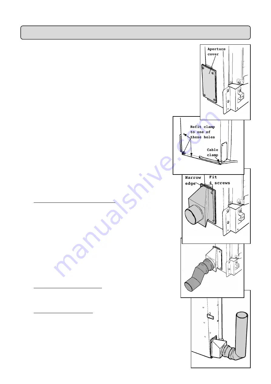
6.6.1

Remove the flue aperture cover and gasket and fit them to the left side

(see figure 11). Be careful not to damage the gasket.

6.6.2

Remove the fan cable clamp from the rear left of the convection box.

Replace the screw thus removed into the convection box.  Clamp the cable
at one of the screws at the right side of the box (see figure 12).

6.7

Fit the flue duct connector to the open side of the convection box

with four tapping screws. The narrow edge of the connecting plate must be
at the back (see figure 13).

6.8

Place the appliance back in position. Secure it to the wall through the

two side brackets using  two woodscrews provided.

6.9

For horizontal duct installations: Fit the “Z” shaped duct coupling to

the duct connector pushing firmly to ensure a good seal. Rotate the
coupling so that its open end is as low as possible (see figure 14).

6.10

For vertical duct installations: Fit an elbow bend duct to the duct

connector pushing firmly to ensure a good seal. (see figure 15).

6.11

Mark the wall at the centre line of the flue duct (54mm above the hearth

for horizontal installations, 200mm from the side of the convection box for
vertical installations). Draw a line at this position along the wall from the heater
to where the fan box hole will be drilled.

P A R T 6 :

G A S   S U P P L Y   &   F L U E   S I T I N G

 Figure 15


 Figure 14


 Figure 13


 Figure 12


 Figure 11

Summary of Contents for Ultimate Turbochim BR517S

Page 1: ...y GB Patent 2 202 622B 600B313 02 M ODEL BR517S G C 3 2 0 3 2 1 2 ULTIM ATE TURBOCHIM S i d e F a n F l u e d I n s e t G a s F i r e I N S T A L L E R G U I D E Please keep in a safe place for future...

Page 2: ...lephone 0345 626341 Local call rates apply P l e a s e l e a v e t h i s I n s t a l l e r G u i d e w i t h t h e u s e r As supplied this appliance is for use with natural gas G20 When converted usi...

Page 3: ...25 Full operating checks 26 27 Control settings check 26 Spillage check 26 27 Flame supervision monitoring system check 27 Final review 28 Servicing parts replacement 29 32 Burner plaques replacement...

Page 4: ...Btu h 6 1kW 20 800Btu h Input Min Gross 2 2kW 7 500Btu h 3 6kW 12 280Btu h Output Max 3 12kW 10 600Btu h 3 6kW 12 280Btu h Output Min 1 1kW 3 750Btu h 1 8kW 6 140Btu h Burner Test Pressure Cold 18 2 0...

Page 5: ...ent and the Welsh Office or the Building Standards Scotland Regulations issued by the Scottish Development Department c All relevant codes of practice d The relevant parts of the current editions of t...

Page 6: ...6 Fig 1 General installation dimensions Surround Cut out Dimensions...

Page 7: ...ht before installing in a timber frame building since the alterations required may nullify any NHBC cover relating to the property If in doubt guidance should be requested from your local authority pl...

Page 8: ...ling 2 11 The appliance must not be installed in any room which contains a bath or shower or where steam is regularly present 2 12 An extractor fan may only be used in the same room as this appliance...

Page 9: ...brick windows etc 300mm B Below gutters soil pipes or drain pipes 75mm C Below eaves 200mm D Below balconies or car port roof 200mm E From a vertical drain pipe or soil pipe 75mm F From an internal or...

Page 10: ...nction box with cable clip earth lead sleeve fixings 1 Fire front casting 1 Strip gasket sealing tape For surround insulation 1 Bottom front cover casting 6 Wood screws plugs 2 Stainless steel screws...

Page 11: ...le tip If there is no spark or incorrect tracking check the spark gap between the electrode wire and thermocouple tip see figure 5 If the spark gap is correct check the ignition wiring 4 3 Remove the...

Page 12: ...he unit slightly forward 3 Detach the control unit cover by removing one screw See figure 10 4 Remove the cable by releasing the cable clamp and detaching the leads from the terminal block and earth c...

Page 13: ...ked positions using a no 10 drill and plug 6 6 For duct connection from the right side 6 6 1 Remove the flue aperture cover and gasket and fit them to the left side see figure 11 Be careful not to dam...

Page 14: ...quired to keep the gap clear of the wall on which the appliance is mounted see section 2 5 1 Drill a 5in 127mm dia hole The interior surface of the wall where the hole is exposed must be finished with...

Page 15: ...in the wall and if applicable the fan box in the recess Push the box in so that the fixing brackets are against the wall and mark the screw fixing positions on the wall 7 5 Remove the fan box Drill t...

Page 16: ...butted together even when covered by the elbow front covers Small children could touch the hot ducting if there are any gaps between the top horizontal flanges or bottom angled flanges of the backing...

Page 17: ...catch in the cable clip slots in the brackets 8 7 Fix the backing plates to the wall The plastic spacing washers must be fitted between the backing plates and the wall Fit using the wood screws provi...

Page 18: ...urround where it passes through the aperture in surround side Wrap the insulating gasket round the duct and secure with the sealing tape supplied as shown in figure 28 8 14 For horizontal duct install...

Page 19: ...19 8 18 Do not block the gap between the top horizontal flange of the duct backing plates and the top rear edge of the front covers see figure 30 Figure 30...

Page 20: ...ld be heard to increase to boost speed within approximately two seconds iii Remove the hand The fan should revert to normal speed after approximately three seconds 9 6 The unit includes a blocked flue...

Page 21: ...holes in the shield with those at the sides of the end plate Secure with the two screws previously removed see figure 33 10 3 Fit the terminal guard see figure 34 Secure the guard at the bottom and a...

Page 22: ...n the on switch Within two seconds the Fan motor should start and the indicator light should go out 11 5 4 Release the on switch The fan should continue to run 11 5 5 Depress the control knob and turn...

Page 23: ...ting a pressure gauge at the test point The test point is on the pipe situated below the bottom right corner of the burner unit See figure 35 Check the pressure with the fan on the appliance alight an...

Page 24: ...Left side R Right side Place the side walls against the sides of the fire box and in the recesses at the sides of the base coals The markings L R should be at the back bottom corners and facing to th...

Page 25: ...control knob depressed for approximately ten seconds to allow the thermocouple probe to warm up and then release it If the pilot does not remain alight ensure that the pilot orifice is clear 13 1 6Wh...

Page 26: ...indows that open to the outside of the building closed Recheck for spillage as above If the smoke is drawn into the appliance continue with the installation If the test is not satisfactory Disconnect...

Page 27: ...the users guide Mention that in windy weather or when the mains voltage is low a slight click may be heard due to the fan control system switching between its normal and boost speeds Advise that if t...

Page 28: ...ve the plaque clamping strips by detaching 6 screws 15 1 3 Remove the plaques and the combination gasket between and under the plaques If necessary remove the gauze and the gasket beneath it 15 1 4 If...

Page 29: ...15 3 5 Disconnect the electrode lead from tab underneath the electrode 15 3 6 Undo the thermocouple nut at the gas tap 15 3 7 Disconnect the pilot pipe from the pilot unit elbow 15 3 8 Remove the firs...

Page 30: ...e the gas tap solenoid unit as sections 15 5 1 to 15 5 12 15 6 2 Make sure that the tap is in the off position 15 6 3 Remove the circlip holding the piezo unit to the tap Remove the piezo unit 15 6 4...

Page 31: ...witch see figure 53 15 10 5 Disconnect the three leads Yellow orange white from the air pressure switch 15 10 6 Disconnect the two leads Brown blue from the mains cable connection block 15 10 7 Replac...

Page 32: ...e weather shield and flue box end plate by removing two screws see figure 55 15 12 3Disconnect the wiring loom connector inside the top right of the flue box see figure 56 15 12 4Slide the fan out of...

Page 33: ...Control knob 1 545979 G Pilot unit For Natural Gas Appliances 1 540979 Pilot unit For Propane Appliances 544929 H Solenoid valve 1 559719 J Burner plaque gasket set 1 569439 K On switch 1 559729 L Off...

Page 34: ...ds Valor is a member of the Society of British Gas Industries which works to ensure high standards of safety quality and performance Careful Installation Valor is a Corgi registered company All our ga...

Reviews: