14
11.5
Connect the other end of the inlet pipe to the elbow
attached to the supply line.
12.
SYSTEM CHECK
12.1
Pressure test the supply line for leaks.
•
The appliance and its individual shut-off valve
must be disconnected from the gas supply
piping system during any pressure testing of that
system at test pressures in excess of ½psig
(3.5kPa).
•
The appliance must be isolated from the gas
supply piping system by closing its individual
manual shut-off valve during any pressure
testing of the gas supply piping system at test
pressures equal to or less than ½psig (3.5kPa).
•
Failure to either disconnect or isolate the
appliance during pressure testing may result in
regulator or valve damage. Consult your dealer
in this case.
12.2
The appliance is preset to give the correct input with
the gas indicated on the rating plate. For input
adjustment, the gas supply pressure to the
appliance inlet must be within the limits stated in
Section 2.3 of this manual.
12.3
The burner manifold pressure is controlled by a
built-in non-adjustable regulator. The correct
pressure range is shown in the table in section 2.3
of this manual. The manifold pressure should be
checked at the pressure test point which is located
on the thermostat unit (see figure 17). The pressure
check should be made with the appliance burning,
the gas control set at “On” and the thermostat
control set at “Full”. (Temporarily refit the control
knobs for checking.)
12.4
All piping and connections must be tested for leaks
after installation or servicing. All leaks must be
corrected immediately.
When testing for leaks :
•
Make sure that the appliance gas control knob is
at the “Off” position.
•
Open the manual shut-off valve.
•
Test for leaks by applying a liquid detergent or
soap solution to all joints. Bubbles forming
indicate a gas leak.
Never use an open flame to
check for leaks.
•
Correct any leak detected immediately.
13.
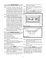
PRESSURE RELIEF SYSTEM CHECK
The appliance is fitted with a pressure relief system. Its
purpose is to allow the safe release of pressure in the
unlikely event of a build up of gas in the fire box before
ignition takes place.
Relief is achieved by the gas pressure pushing open the
two spring loaded plates under the fire box below the front
burner. This allows some gas to escape safely. The plates
will then return to their closed position (see figure 21).
14.
AERATION SETTING CHECK
On natural gas and propane appliances both front and rear
burners are equipped with adjustable aeration shutters to
control primary aeration.
For the natural gas appliance both front and rear burner
shutters are set fully open.
For the propane appliance the front burner shutter is set
fully open and the rear shutter partially closed.
For the majority of installations the above settings will be
correct and the shutters should not be adjusted. In a few
instances performance may be improved by adjusting the
aeration. This will not be able to be properly determined,
however, until the appliance is operated with the logs and
window installed.
Fig. 21 Pressure relief system check
Summary of Contents for Legend 936XN
Page 6: ...6 WITH PLINTH WITH LEGS Fig 2 Dimensions clearances ...
Page 15: ...15 ...


