


INSTALLER’S GUIDE
Page 40
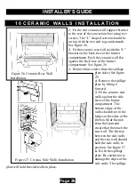
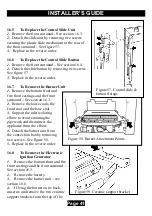
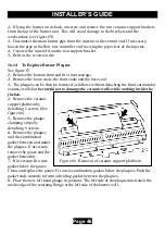
Figure 56. Front surround top
location
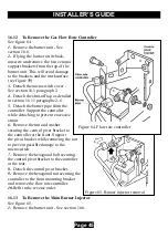
Figure 55. Control linkage
disconnection
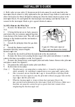
Figure 54. Front Surround
Bottom Location
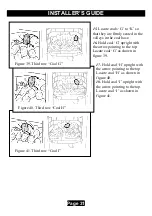
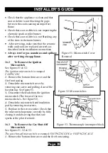
2.
Detach the microswitch cover by removing one
screw and pulling clear of the location lug. See figure
51.
3.
Loosen the thermocouple nut to free the
microswitch leads and pull the leads clear of the
thermocouple interrupter block. See figure 53.
4.
Detach the bridging bracket, microswitch assembly
and insulation pad by removing two screws. See figure
52.
5.
Replace in the reverse order. When refitting the
leads to the interrupter block, make sure that they are
secured firmly to give a good electrical contact.
16.4
To Remove the Fire Front
Surround
1.
Remove the bottom front cover and the fire
front casting.
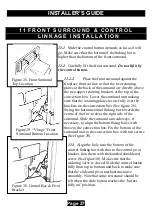
2.
Detach the control-linking bar from the
control pivot bracket by removing the knurled
screw, which joins the control linking bar to
the control pivot unit. See figure 55.
3.
Remove the two screws securing the bottom
of the front surround to the sides of the
convection box. See figure 54.
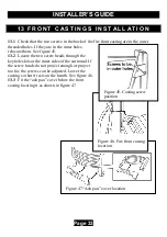
4.
Make sure that the control linking bar
has been detached (See 2 above)
.
Carefully
lift the surround unit upward to clear the upper
retaining brackets on the convection box - See
figure 56. Pull the surround clear and place
carefully aside.
5.
Refit in the reverse order. Make sure that the
surround is properly located over the upper
retaining brackets. See section 11 of this manual
for detailed fitting instructions.


