background image

Check that the appliance is clean and that

soot or debris is not blocking the gaps
between the ceramic fuel effect pieces causing
an imperfect flame.

Check that soot or debris is not impairing

the electrode spark or pilot burner.

Check that soot or debris is not blocking

any of the holes in the main burner.

After servicing, make sure that the

ceramic fuel effect pieces are replaced
correctly as described in the installation
instructions.

Always test for gas soundness and

spillage after servicing the appliance.

16.1 To Remove the Fire Front
Surround

1. 

Remove the upper surround trim,

lower surround trim and side surround
trims. These are held by magnets.

2.

The surround is held in place by four

retaining plates at the back of the 
surround. These slot into four retaining
brackets on the hotbox. To remove the 
surround, hold the sides of the
surround and lift upward and forward.
The surround should lift clear of the
hotbox (See figure 40)

3.

Replace the surround and trims as in

section 12.

16.2 To Remove the Burner Unit

1.

Remove the Firefront surround as in 

Section 16.1.

2.

Remove the ceramic fuel effect pieces.

3.

Detach the spillage plate from the

hotbox by removing the four screws (See 

Page 38

INSTALLER GUIDE

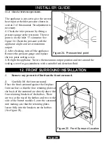
Figure 42. Removal of Inner reflector

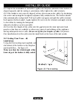
Figure 41. Spillage plate removal

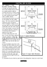
Figure 40. Front surround removal

Summary of Contents for Equinox 754

Page 1: ...se leave this guide with the owner THIS APPLIANCE IS FOR USE WITH NATURAL GAS G20 THIS APPLIANCE IS SUITABLE ONLY FOR INSTALLATION IN THE UNITED KINGDOM GB AND THE REPUBLIC OF IRELAND IE Valor Heating...

Page 2: ...s a member of the Society of British Gas Industries which works to ensure high standards of safety quality and performance Careful Installation The manufacturer is a CORGI registered company This gas...

Page 3: ...ONT SURROUND INSTALLATION 29 13 CERAMIC PEBBLES INSTALLATION 31 14 FULL OPERATING CHECKS 34 14 1 Check the Control Settings 34 14 1 1 Lighting the burner 34 14 1 2 Operating the burner 34 14 2 Check F...

Page 4: ...nd not your back Avoid twisting at the waist It is better to reposition your feet Avoid upper body top heavy bending Do not lean forward or sideways whilst handling the fire Always grip with the palm...

Page 5: ...waste This is not classified as hazardous waste and may be disposed of at a tipping site licensed for the disposal of industrial waste Protective clothing is not required when handling these articles...

Page 6: ...o be in accordance with All the relevant parts of local regulations All relevant codes of practice The relevant parts of the current editions of the following British Standards BS 715 BS 1251 BS 1289...

Page 7: ...th BS1251 after removal of the fireback and sufficient material behind the fireback for a debris catchment space The required fireplace hearth debris catchment area and clearance dimensions are shown...

Page 8: ...that faults such as cracking may be caused by poorly built and restrictive flues e g mortar extrusions too many bends flue heights below three metres restrictive terminations etc 4 2 4 If the firepla...

Page 9: ...must not be used for any other appliance or application 4 6 Any chimney damper or restrictor should be removed If removal is not possible they must be secured in the open position 4 7 If the applianc...

Page 10: ...top surface of the hearth to the underside of any shelf made from wood or other combustible materials is shown below For a shelf up to 150mm deep Minimum height 700mm For a shelf deeper than 150mm Min...

Page 11: ...tion is available 4 16 If the appliance is to be fitted against a wall with combustible cladding the cladding must be removed from the area covered by the outer surround The cladding must also not tou...

Page 12: ...consumer should be informed to stop using the appliance until the installation and appliance have been thoroughly checked The A S D will shut the appliance down if an unacceptable amount of harmful pr...

Page 13: ...Page 13 INSTALLER GUIDE...

Page 14: ...Ceramic support rods 2 Small U seals for hotbox side flanges 1 Strip of floor sealing tape 6 Fibre plugs 4 Woodscrews 2 Fire retaining cables 2 Cable clamps 4 Eyebolts 1 Rubber grommet 1 Smoke match t...

Page 15: ...Page 15 INSTALLER GUIDE Figure 6 Pack contents...

Page 16: ...ing must be removed from the area covered by the outer surround The cladding must also not touch the surround See figure 4 We suggest that the actual surround is used as a template to mark the area fo...

Page 17: ...l or equivalent insulation See figure 2 6 2 Fireplace Flue Pull Close all doors and windows in the room in which the appliance is to be installed After confirming with a match that smoke is drawn into...

Page 18: ...ector can be rotated to allow a connection from any direction The T connector includes a valve for isolating the gas supply and a pressure test point The supply pipe must be rigid material Flexible pi...

Page 19: ...ner reflector See figure 10 4 Carefully lift the inner reflector and pull forward to remove Be careful not to scratch the top surface of the burner cover See figure 10 The reflector may spring a littl...

Page 20: ...section seals to the bottom edges of the hotbox side flanges See figure 12 11 It is important that the grommet supplied in the loose parts pack is fitted to the hole in the rear of the convection box...

Page 21: ...the two supplied with the fire 14 This appliance is supplied with a flue restrictor for use where the flue draught is excessive The restrictor must NOT be fitted where a precast flue or a flue liner i...

Page 22: ...seal Be careful not to stretch the seal when measuring Remove the protective backing from the foam seal and fit this to the rear of the top flange See figure 15 Cut two 580mm lengths Fit these to the...

Page 23: ...hotbox into the fireplace feeding the supply pipe through the pierced hole in the rear grommet 3 Mark the fireplace front surround through the four fixing holes in the side flanges of the hotbox See...

Page 24: ...opening when tension is applied to the cables 3 Insert a fibre plug into each hole Use the fibre plugs supplied with this appliance Never use plastic plugs instead of the fibre plugs supplied Screw th...

Page 25: ...se of the hotbox using a no 12 masonry drill See figure 20 9 Insert a fibre plug into each hole Use the rawlplugs supplied with this appliance Never use plastic plugs instead of the fibre plugs suppli...

Page 26: ...y tension to the cables by turning the hexagonal adjusters clockwise as far as possible 14 Feed the free length of the cables into the gap between the inner and outer back panels so that they are avai...

Page 27: ...or isolating the gas supply The supply pipe must be rigid material Flexible pipe must not be used Connect the supply line to the appliance Turn on the gas supply and pressure check the installation pi...

Page 28: ...ol knob depressed and hold the pilot ignition position for five seconds When the control knob is released the pilot flame should remain lit If there are no sparks check that the electrode lead is conn...

Page 29: ...the maximum output position and test around the sealing screw for gas soundness with a suitable leak detection fluid 12 FRONT SURROUND INSTALLATION 1 Remove any protective film from the front surround...

Page 30: ...3 2 The trim sections are held in place using 8 magnets Position the magnets as in figure 26 Note that the magnets on the bottom and top trim are inside of the cutout This will ensure that the bottom...

Page 31: ...front base pebble in front of the burner See figure 30 2 The rear base pebble has the letters MB on the underside Locate the rear base pebble behind the burner See figure 31 Page 31 INSTALLER GUIDE F...

Page 32: ...te the second pebble 5 centrally between the right hand ceramic support rods See figure 33 They will now be positioned directly above the burner ports 5 Pebble 3 has a location peg on the underside Th...

Page 33: ...t rods See figure 36 Leave a gap between pebble 3 and the pebble 1 This will allow the pilot flame to be viewed 8 There are two pebbles numbered 2 on the underside Locate these on the pebble base betw...

Page 34: ...to the pilot ignition position A click will be heard as the integral piezo operates A flame should appear at the pilot to the left hand side of the pebble base When a flame appears at the pilot keep...

Page 35: ...ue restrictor See section 9 point 14 remove the restrictor reseal the appliance and retest If smoke is still not drawn into the appliance disconnect the appliance and seek expert advice 5 If the above...

Page 36: ...re surface Front surround Clean the metal parts with a slightly damp cloth and then dry If this does not work apply a very small amount of baby oil to a lint free non abrasive cloth and wipe over the...

Page 37: ...an isolating valve It is recommended that at least once a year the appliance is disconnected and the fireplace opening checked and cleared of any debris This product uses fuel effect pieces containing...

Page 38: ...move the upper surround trim lower surround trim and side surround trims These are held by magnets 2 The surround is held in place by four retaining plates at the back of the surround These slot into...

Page 39: ...r to avoid straining the pipework and disconnect the appliance from the T connector 10 Detach the burner unit from the hotbox by lifting clear 11 Replace in the reverse order 16 3 To Remove the Pilot...

Page 40: ...gas valve to the mounting bracket 10 Remove the gas valve 11 Refit in the reverse order 16 5 To Remove the Piezo Generator 1 Remove the gas valve as section 16 4 2 Make sure that the tap is in the of...

Page 41: ...from the burner clamping plate See figure 46 4 Lift the right hand side of the burner slide it to the right and lift clear 5 Refit in reverse order 16 8 To Remove the Main Burner Injector See figure...

Page 42: ...EY DESCRIPTION NO OFF PART NO A Control valve spark generator 1 5108221 B Spark generator and circlip 1 5108923 C Pilot unit 1 3002988 D Injector Stereomatic Cat 82 065 1 5108138 E Burner 1 5108827 F...

Reviews: