18
6. Set the Adjust Mode as the No Adjustment when using regular roll media.
7. Set the Weight as the Labels 2 when using regular matt papers(art papers).
Page 1: ...Valloy Incorporation Any 001 User Manual Anytron Digital Color Label Press...
Page 2: ...ery 9 3 2 Installation of the press station 9 3 2 1 Checking of press station components 9 3 2 2 Checking of place carrying and installation 9 3 2 3 Checking of Various plug ins and operations 9 3 3 I...
Page 3: ...tion of process after printing 38 9 Maintenance and Management 39 9 1 Overview 39 9 2 Types of errors on the printer press LCD messages and its description 39 9 3 Checking thereplacement cycle of cons...
Page 4: ...socket and a multi consent with an earth terminal 1 2 2 In use Do not carry out inspections or repairs except if you are a qualified persons Do not disassemble arbitrarily or subject the machine to i...
Page 5: ...4 1 3 Legal validity of this document We inform you that this manual does not carry legal binding force and we reserve the right to change this manual at will without giving a separate notice...
Page 6: ...feed the printer which allows the paper to keep its tension constant 1 2 Unwinder Tension Bar Sensor bar for feeding paper When paper is fed up to the printer the tension bar would be moved up by the...
Page 7: ...on Button for operating the rewinder 11 5 Feed Button Button for operating the feeding roller 5 moving paper backward 6 Feed Button Button for operating the feeding roller 5 moving paper forward 1 9 S...
Page 8: ...Tray for using continuous media 2 5 Front Cover Release Lever The front cover is opened by pulling the lever 2 6 PowerSwitch On Off Switch Printer power switch 2 7 AC Power Socket Connection for print...
Page 9: ...it should be installed in a place satisfying the specified conditions for temperature humidity In addition considering the gross weight of this product it should be installed on a level rack that can...
Page 10: ...than being a simple rack to put a printer on Therefore the same care is required as with the printer digital press when moving or installing it so please follow understand the installation personnel...
Page 11: ...ion and then secure the printer and the mechanics together tightly with bolts in the box refer to the figure Checking Existence of Various Consumables Toner Cartridge Transfer Belt Fuser and Mounting...
Page 12: ...11 Check the IP refer to 4 1...
Page 13: ...12 4 Installation of the Printer Driver 4 1 Installation of the Driver 1 Execute Device and Printer on the start menu 2 Click Add a Printer on the activated window 3 Click Add a Local Printer...
Page 14: ...Port of Make a New Port and then click Next when using LAN 5 After entering a printer s IP address click Next Refer to the 3 3 Installation of the printer for checking the printer s IP 6 Click Have Di...
Page 15: ...licking Computer on the finding location select Anytron Driver in the Anytron media device and then click the Open 9 Click OK 10 After checking the OKI WEB61 click Next 11 After entering a printer nam...
Page 16: ...Next 13 After selecting Set as the Default Printer click Checking a Test Page for checking the connection There should be A4 papers in the tray 1 14 The installation will be completed when pressing C...
Page 17: ...iver 1 After right clicking the Anytron driver in the Devices and Printers click the Default Print Setup 2 Set the Size as the Super Long Paper in the Default Print Setup 3 In the message box opened a...
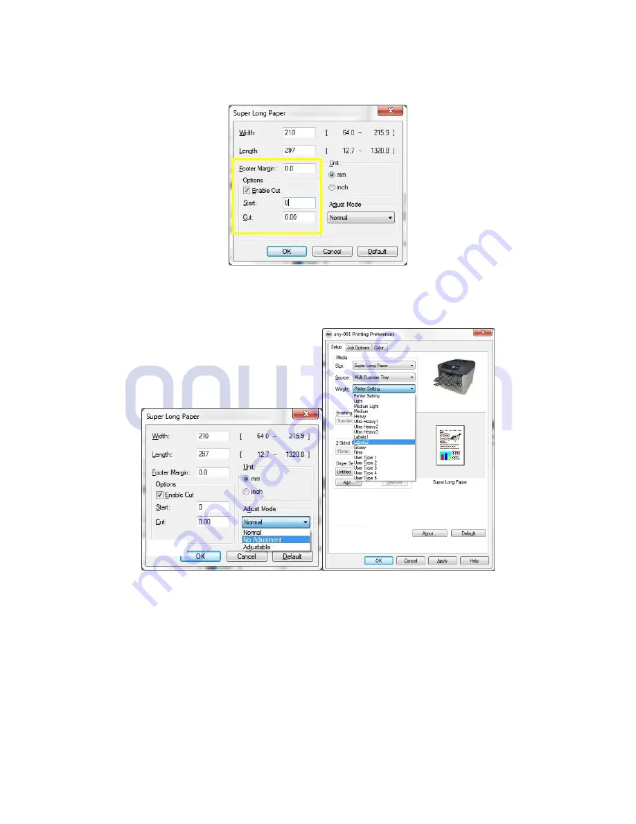
Page 18: ...sired printing edit size into the Width Length Ex A4 size print 210x297 5 Footer marginthe space between printed units Start is the beginning point of the images andcut is the cutting point after fini...
Page 19: ...18 6 Set the Adjust Mode as the No Adjustment when using regular roll media 7 Set the Weight as the Labels 2 when using regular matt papers art papers...
Page 20: ...ck mark once at the beginning No Adjustment X Print continuously without using the sensor Default Adjustable O Print consecutively by sensing every image unit s black mark continuously Mode to support...
Page 21: ...ed if you enter the number of output as 9 This is equally applied in Adjustable mode When printing 100mm image adjust location at every 5 sensing 4 5 Inquiry and Download If you need more information...
Page 22: ...on of the Roll Continuous Paper and Cautions 6 2 How to Mount Basic 215mm Paper 1 After pressing 215mm paper to the unwinder s left guide and mounting it turn the knob A to fix the paper 3 Check the g...
Page 23: ...viewed in the photo fasten the lever A 5 Press the Feed button on the right of the panel to move paper to the printer s entry 6 Mount an empty paper jointing tube of 215mm on the rewinder 7 After moun...
Page 24: ...th tapes 9 When printing shaft2 and tension bar of Unwinder are very hot A high temperature warning label is attached so please DO NOT TOUCH the part 10 When pressing the REW rewinder button on the pa...
Page 25: ...is is the guide for aligning paper Four guides are required for aligning 6 inch paper 3 Move the guide up to the 6 inch marking of the unwinder bobbin At this time the groove A on the guide should be...
Page 26: ...de also on the other side 6 Turn the knob to fix the bobbin s paper and the guide 7 This is the unwinder mounting 6 inch paper 8 Fix the guide matching with 6 inch also on the shaft grid marking of th...
Page 27: ...26 10 Fix the guide matching with 6 inch also on the shaft grid marking of the rewinder 11 Mount a 6 inch paper jointing tube also on the rewinder identical to the unwinder...
Page 28: ...releases the roll paper by rotating at a speed proportional to the extent of the tension bar s moving up 4 When pressing the rewinding button after fixing the paper printed out on the paper jointing t...
Page 29: ...28 7 When printing is completed the cutter cuts the paper 8 If you want to print again use the Feed button to move the paper to the printer s entry...
Page 30: ...illustrator Make two vertical lines 90 of 200mm with two lines of the tool box 2 Align the two lines as the figure respectively Align them at 5mm inside the base sheet 3 While printing about 2 3m 10 1...
Page 31: ...n equal margin at the both side If the margins are not the same adjust the unwinder s guide to print them identically 5 If the operating line is printed at the center put the media on the rewinder to...
Page 32: ...o Use the Basics of Illustrator for Any 001 1 Create a new file with a width of 215mm and a desired height Ex 215 x 250 mm 2 Make a black mark of 6 x 6mm on the top left of the base sheet 3 Fetch an i...
Page 33: ...32 4 The RIP converts it into a printable file Save the file as an PDFformat...
Page 34: ...o save time and costs 7 2 1 Adjustment of the Sensor s Location and how to auto sensing Can choose the black mark sensor or gap sensor as an option How to auto sensing of Black mark sensor As the phot...
Page 35: ...etting would be completed How to check the sensor is normally set Move the paper back and forth to sense the black mark for checking whether it is normally set At this time if the sensor s LED is turn...
Page 36: ...ou may use the Gap Sensor by putting up sensor alter switch You may use the Black Mark Sensor by putting down sensor alter switch Check if sensor is normally operated Please refer to 7 2 1 7 2 3 Setup...
Page 37: ...setting a value of the Start option as 50 5mm The first page would be printed from 50 5mm after sensing the black mark and the remaining pages are regularly printed at intervals of a page 7 2 4 How t...
Page 38: ...le data may be created Here enter more than 2 Footer Margin value when you configure printer driver as shown in the above example Footer Margin Footer Margin in adjustable mode is a sensing area and l...
Page 39: ...inating 8 1 Digitalization of process after printing It is an Any Cut equipment for precision laminating die cutting of roll printed through Any 001 For details related to Any Cut please visit www any...
Page 40: ...lacing 9 3 1 Checking of consumable s replacement cycle Installation Personnel Name Tel 1 If the printer is connected through Ethernet you may check the residual quantity of consumables by entering IP...
Page 41: ...dge a few times to evenly distribute the toner powder This will enable you to obtain the best yield from your toner cartridge CAUTION To avoid toner wastage and possible toner sensor errors do not cha...
Page 42: ...e right hand end of the cartridge and then draw the cartridge to the right To release the left hand end as shown and withdraw the toner cartridge out of The printer 3 Put the cartridge down gently ont...
Page 43: ...material and peel off the adhesive tape from the underside of the cartridge 8 Holding the cartridge by its top centre with the coloured lever to the right lower it into the printer over the image drum...
Page 44: ...oured lever towards the rear of the printer This will lock the cartridge into place and release toner into the image drum unit 11 Gently wipe the LED head surface with a clean lint free cloth 12 Final...
Page 45: ...e and open the printer s top cover fully 2 Note the positions of the four toner cartridge a and image drums b It is essential that they go back in the same order 3 Holding it by its top centre lift th...
Page 46: ...e drum unit 6 Lift the right hand end of the toner cartridge 1 and then draw the cartridge to the right to release theleft hand end as shown 2 and withdraw the toner cartridge out of the image drum ca...
Page 47: ...umunit and release toner into it 10 Holding the complete assembly by its top centre lower it into place in the printer locating the pegsat each end into their slots in the sides of the printer cavity...
Page 48: ...drum units out of the printer and place them in a safe place away from direct sources of heat and light CAUTION The green image drum surface at the base of each cartridge is very delicate and light s...
Page 49: ...rinter Locate the drive gear into the gear inside the printer by the rear left corner of the unit and lower the belt unit flat inside the printer 8 Turn the two fasteners a 90 to the right until they...
Page 50: ...cover 1 Press the cover release and open the printer s top cover fully 2 Identify the fuser handle a on the top of the fuser unit 3 Pull the two fuser retaining levers b towards the front of the prin...
Page 51: ...latches closed 9 3 2 5 Clean the LED HEAD Clean the LED heads when printing does not come out clearly has white lines or when text is blurred There is no need to switch off the printer to clean the le...
Page 52: ...51 9 4 Purchasing of Consumables Please refer to the Anytron home page at www Anytron net 9 5 Inquiry and Download Please refer to the Anytron home page at www Anytron net...
Page 53: ...length 656feet 200meter Paper size Min 3 x 5 inch Max 8 5 x 4800 inch Continuous Papers width 8 5inch 215mm Margin of error Cut sheet 0 4 mm Continuous paper No adjustment Beginning 3M 0 8 mm After 3M...
Page 54: ...0kg 22lbs Auto cut Automatically cut after printing job Also manually cut sheet feeding sheet feeding and printing are available Pre cut label printing on pre cut label and pre printed label is availa...
Page 55: ...and inquiry If you need any more information on the product and A S service visit our home page at www anytron net or contact us by phone or email VALLOY Incorporation Room 403 Haeju Bldg 639 5 Ilwon...