


VALLEY FORGE & BOLT MANUFACTURING COMPANY
Phone: (602) 269 - 5748
4410 W. Jefferson St.
•
•
•
•
Phoenix, AZ 85043
•
•
•
•
USA
Fax:
(602) 269 - 7851
SPC4
TM
SYSTEM
•
•
•
•
MODEL 600A
•
•
•
•
USER'S MANUAL
Rev. 1.1
- Page 9 of 27 -
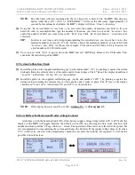
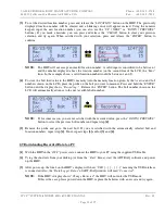
Please see “
Figure 1.3.3 -
Liquid Crystal Display (LCD)
”.
-.
1
.-
- CURRENT DATE IN MM/DD/YY FORMAT
This area of the LCD shows the current date in MM/DD/YY format. The current date can only be
changed on the HHU when the HHU is connected to a PC running the ABT-DAQ software (can not be
changed using HHU’s keypad).
-.
2
.-
- CURRENT TIME IN HH:MM:SS FORMAT
This area of the LCD shows the current time in HH:MM:SS format. The current time is displayed in the
“military” format (00:00:00 to 23:59:59, no AM/PM). The current time can only be changed on the
HHU when the HHU is connected to a PC running the ABT-DAQ software (can not be changed using
HHU’s keypad).
-.
3
.-
- MAXIMUM NUMBER OF LOCATIONS / BOLTS
This area of the LCD shows the maximum number of locations / bolts the HHU is set to accept. These
numbers can only be set when the HHU is connected to a PC running the ABT-DAQ software (can not
be changed using HHU’s keypad). The HHU has a maximum storage capability of up to 13,100 records
(1 bolt reading per record). To make it easier for the operator and to save time, these records can be
further divided between a number of “
locations
” and “
bolts
”.
For example, let’s suppose we want to record data from a mill having 5 flanges with 20 bolts per flange.
Every flange should be assigned to a
location
number (1 through 5) and every bolt from any flange will
be assigned a
bolt
number (1 through 20) – for a total of 100 bolts. Using the ABT-DAQ software set
these numbers of
locations
and
bolts
. In the field, if the operator starts with the flange number 1, bolt
number 1, the HHU’s display will automatically go to the next
bolt
and respectively to the next
location
(flange) when all the bolts from one flange have been recorded.
-.
4
.-
- CURRENT LOCATION / BOLT NUMBER
This area of the LCD shows the current record number the HHU is ready to acquire. The numbers
shown here will automatically advance to the next available record after every data acquisition event.
First, the
bolt
numbers, and after the maximum number of bolts for the current
location
has been
reached, the
location
number. The operator can also set these numbers in an out of order fashion using
the “
BOLT
”, “
LOCATION
” buttons and the numerical keypad. To advance to one of the next bolts (or
to go back to a previous bolt), the operator can also press the “
UP | NEXT
” or “
DOWN | PREVIOUS
”
buttons.
-.
5
.-
- CURRENT LOAD / OTHER MESSAGES
This area of the LCD shows the load read by the probe at any given time. It can also show other
messages (i.e. “
No Probe Found
” when the probe is not attached to a fastener).


