background image

OMNIA 

50 


8


ROUTINE MAINTENANCE 

Very little maintenance is required, and it is limited to the operations detailed in the following paragraphs.  

CAUTION!  Please  disconnect  the  machine  from  the 

electrical

  mains  supply,  before  carrying  out  any 

maintenance operations 


8.1


CLEANING 

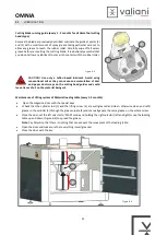
One of the most important maintenance tasks is the frequent and complete cleaning of the following parts:  

Worktable (daily) 


Clean the top of the work table everyday with compressed air or with a soft and dry brush. 


Electrical panel fan and the base (every week) 


Switch off the machine. 


Remove the air filter cover using a 
screwdriver  


Blow the fan and the air filter with 
compressed air.  


Reinsert the filter inside the cover and 
fit it into the seat under the fan. 


Cutting head (Everyday) 


Clean  the  cutting  head  using  compressed  air  or  with  a  soft  dry  cloth  to  remove  dust  and  any  debris  left  from 
production. 


Check for, and remove, any dirt on the blade protection holder. 


DANGER! 

Before cleaning the cutting tools remove the blade to avoid any accidental injury. 


Vacuum pump cleaning. 

Before carrying out any operation, switch off the machine and disconnect it from the mains power supply. Follow the 
instructions provided with the pump documentation. To access the pump, remove the machine protection panel 
(Figure 5-22). 


Figure 8-1


Summary of Contents for OMNIA

Page 1: ...OMNIA Instruction and Maintenance Manual...

Page 2: ......

Page 3: ...INSTALLATION OF THE MACHINE 9 3 INTRODUCTION 10 3 1 MACHINE DESCRIPTION 10 3 2 CUTTING TOOLS 11 3 3 PEN PLOTTING TOOL OPTIONAL 12 3 4 CREASING TOOL OPTIONAL 13 3 5 VERSATOOL OPTIONAL 13 3 5 1 Intercha...

Page 4: ...the creasing tool 43 6 7 8 Fitting a cutting blade versatool optional 43 6 7 9 Repalcying the foot roller on white head versa tool optional 44 6 7 10 Head access 45 6 7 11 Mounting tool 45 6 7 12 Asse...

Page 5: ...machine Please ensure that our safety and general operating instructions are strictly followed 1 2 CONVENTIONS USE IN THIS MANUAL To ensure safe and accurate usage of the machine as well as to prevent...

Page 6: ...posed to water rain or snow Such locations may cause electric shock or create a fire hazard due to current leakage If the machine generates smoke overheats emits a strange odor or otherwise functions...

Page 7: ...ting plotter When disconnecting the power cord or interface cable do not pull on the cord cable Such action will damage the cord cable resulting in a fire hazard or possibly an electric shock Do not c...

Page 8: ...or written permission from the company 1 8 SCOPE OF THE INSTRUCTION MANUAL This instruction manual is an essential part of the machine and its scope is to provide all the information necessary to Safe...

Page 9: ...s included in this manual will or could result in the loss of warranty As part of it s continuing quality improvement programme VALIANI S r l reserves the right to carry out modifications it believes...

Page 10: ...NINGS 2 1 LABELS PRESENT ON THE MACHINE The machine is fitted with various labels to show either data or safety concern areas for the operator Referring to the photograph below these are 1 4 3 6 2 4 5...

Page 11: ...he machine LABEL 2 Adhesive label Hand Entanglement Rotating Gears warning LABEL 3 Adhesive label Rotating gears warning LABEL 4 Adhesive label Moving parts warning LABEL 5 Adhesive label Hand cut war...

Page 12: ...tton see paragraph 6 of this manual 4 Optional operator safety mats fixed to the floor with screws 5 Electrical panel door mobile guard closed with a key 6 Loader door mobile guard closed with a key 7...

Page 13: ...achine is stopped the EMERGENCY button must be pressed to put the machine into suspend mode before doing any maintenance work including adjustments NOTE Before doing any maintenance to the electrical...

Page 14: ...1 MACHINE DESCRIPTION The Omnia consists of a loader the machine that performs the processing and an unloader to be assembled on site for easier transportation see paragraph 5 The depth of the cutting...

Page 15: ...e L100B 002156 Multipurpose T16 Blade 38 Angle Universal knife for soft materials To make sharp edges 002157 Multipurpose T17 Blade with a tighter angle for greater precision on cuts with a small radi...

Page 16: ...with a tighter angle for greater precision on cuts with a small radius 25 Angle Sole leather cardboard thin polyester To make sharp edges 002445 T18 Heavy Duty Blade Very rigid materials sole leather...

Page 17: ...ional tools therefore minimizing delay during the working process Figure 3 6 The creasing set consists of 9 tools each with different characteristics 1 Perforatingtool 32mm 1 26 Serrated cut wheel 2 1...

Page 18: ...d purple for pressing in relief The embossing head is designed for decorating in relief Whatever design corner or clip art it can be elegantly pressed in relief on a mountboard by using the pressure o...

Page 19: ...690kg 1521lbs Loader weight 220Kg 485bs 260kg 573lbs Sound emission 78dB Connectivity Ethernet USB DATA Buffer External PC File Formats SVG PLT DXF CF2 PDF HPGL XML Tool Change Manual No Tools Holder...

Page 20: ...he machine This figure will be properly trained by the Valiani technician Maintenance technician The maintenance technician manages machine maintenance and repairs therefore it can also perform extrao...

Page 21: ...e should only be moved using suitable machinery for the task forklift truck pallet truck The machine can be transported by Check that the machine has not been damaged while being transported If there...

Page 22: ...s as described in the following section 5 INSTALLATION 5 1 UNPACKING THE MACHINE Carefully remove the corrugated cardboard box trying not to damage it it may need to be re used until the contents are...

Page 23: ...hematized below Figure 5 2 Warning The installation of any element that could compromise the visibility and supervision of the machine operator is not allowed Note Make sure there is at least 60 cm of...

Page 24: ...below for the unloading and assembly of the machine DANGER Make sure that the forklift used can carry the weight of the machine and that the forks are long enough to exceed completely under the load...

Page 25: ...Disassemble the shipping bracket by unscrewing the 8 screws pointed in the figure paying attention to not pull the electrical cables DANGER Hold the PC arm while disassembly in order to avoid the ris...

Page 26: ...ng screw 2 Move the beam by pushing it forward in order to free the locking pin make sure that the casing does not remain hooked to the pin while moving if necessary pull the casing slightly upwards t...

Page 27: ...below for the unloading and assembly of the loader DANGER Make sure that the forklift used is able to carry the weight of the machine and that the fork blades pass completely under the load Nr 4 Adjus...

Page 28: ...enance see par 13 Raise or lower the feet of the machine in order to ensure a level work surface Screw in and tighten the foot lock nut Figure 5 11 Remove the 6 screws indicated to free the operator s...

Page 29: ...OMNIA 25 Figure 5 14 Remove the protective covers from the loader by unscrewing the locking screws Figure 5 15...

Page 30: ...of the loader Couple the loader with the machine by screwing and tightening the 6 screws removed previously Figure 5 14 Remove the two screws from the transmission protection supports Figure 5 17 Refi...

Page 31: ...d mount it with the relative screws washers nuts do not over tighten the nuts the slide must be able to rotate freely Screw the two knobs with washers on the sides of the slide by passing them inside...

Page 32: ...m with the relative knobs and washers 5 7 ELECTRO PNEUMATIC AND DATA CONNECTIONS Once the mechanical assembly has been completed carry out the electro pneumatic and data connections following the step...

Page 33: ...n previously tested and the rated voltages verified Turn on the power master switch Check that all the emergency buttons are not pressed and if they are reset them Paragraph 6 1 Press the power button...

Page 34: ...nected to the compressor Once connected to the compressor or to the air network check that at least 7 Bar 101 5 PSI is indicated on the pressure regulator 3 WARNING The pressure supplied by the compre...

Page 35: ...off and disconnected from the mains power supply Arrange the safety mats on both sides of the machine with the cables exiting towards the machine as shown in the diagram Figure 5 28 Model A B C D E O...

Page 36: ...re 5 22 Figure 5 29 Pass the connection cables under the machine until they enter the base through the appropriate opening Once inside connect the connectors to the relative pins on the side of the el...

Page 37: ...diately stop the machine in case of DANGER to the operator or risk for the machine itself Each button has a mechanical stop to prevent the operator from accidentally pressing it again To reactivate no...

Page 38: ...vates suction it is extended to the corresponding sectors of the table Figure 6 3 Note Switching on the pump does not directly produce suction on the surface as this is controlled via software Note If...

Page 39: ...6 Constant red Warning Emergency buttons pressed pressure on safety mats compressed air pressure is low disconnected auxiliary or thermal switches on the electrical panel Flashing red Alarms reset rea...

Page 40: ...switched on and connected to the PC before opening V Studio From V Studio control panel click on SmartCut once the connection has been established make the machine ready using the ROXY button Lower t...

Page 41: ...mode MAN Figure 6 4 then keep the Up Down selector in the Down position to lower the loading surface Position the materials to be processed on the loading surface so that they are pushed against the s...

Page 42: ...ing the material pay attention to the side with a width between 200 and 340 mm touches the front of the feeder the left side touches the reference plate Point 0 nr 1 Then place the movable stops on th...

Page 43: ...terial aligned Warning As we previously did make sure to do not position the movable stops beyond the line drawn on the surface B as they could interfere with the reading of the photocells After placi...

Page 44: ...sume the procedure from point b b Loosen the set screw 8 and extract the blade holder 9 c Insert the desired blade holder with the reference pin 10 oriented as shown in the figure and make sure that i...

Page 45: ...matches the locking screw and then push it inside until to the stop and tighten the screw 3 Position the blade guard A or B depending on whether we have chosen a TC5 10 15 or TC25 type paying attentio...

Page 46: ...blade locking set screws 3 with a 1 5mm Allen key Position the blade guard so that the reference pin 4 matches the sliding slot 5 then grab it from the sides 6 and push it towards the tool Attention...

Page 47: ...otect it if necessary to avoid cutting During reassembly use a rubber object to keep it in its housing during tightening of the locking screw Disassemble the head see chapter 6 7 13 Remove the blade h...

Page 48: ...t to keep it in its housing during tightening of the locking screw To replace the roller with the presser foot and vice versa proceed as follows Disassemble the head see chapter 6 7 13 Remove the blad...

Page 49: ...MOUNTING TOOL The cutting tools A B have to be fitted to head holder 1 while the creasing C penholder D and VersaTool E have to be fitted to head holder 2 It is not possible to invert the tools Use t...

Page 50: ...ect position as shown in the diagram below Note The pin Y1 must coincide with the slot Y2 Once inserted tighten the previously mentioned socket head screws L and M and insert the male air connectors F...

Page 51: ...with another one proceed as follows Loosen the screw Z Figure 6 29 hold the release tool fork 1 by its handle and insert it into the slot located in the top part of the head Holding the tool with one...

Page 52: ...head register 2 anticlockwise to increase or clockwise to decrease the blade cutting depth Then tighten knob 1 To adjust the creasing pressure you should loosen the knob 3 turn the register 4 anticlo...

Page 53: ...in place OFF then reassemble the protection glass with the four screws removed previously To perform a Kiss cut with VersaTool the switch K must activate by moving into KISS CUT ON mode K 7 4 ADJUSTIN...

Page 54: ...e machine Remove the air filter cover using a screwdriver Blow the fan and the air filter with compressed air Reinsert the filter inside the cover and fit it into the seat under the fan Cutting head E...

Page 55: ...r dust scraps on the cutting head guides and could leave traces of oil on the material being cut Maintenance of Lifting system of Material loading table every 1 2 months Open the magazine door with th...

Page 56: ...figure 3 An oil suitable for a pneumatic system with a viscosity of ISO VG 32 or max 46 is recommended Re insert the cap 4 and tighten gently Attention Over tightening could break the tank s thread g...

Page 57: ...replacement Make sure that the machine is turned off and disconnected from the mains power supply Dismantle the two protection strips by removing the relative fixing screws Figure 5 12 and Figure 5 13...

Page 58: ...then loosen the lock nut 2 and then the adjustment screw 3 until the head rests on the surface Pay attention to the sensor cable Repeat the operation on the opposite side of the table With the help of...

Page 59: ...two edges of the new belt and fit the junction links so that alternating they do not end with two consecutive links on the same side of the belt Insert the joint pin and bend the two ends as shown in...

Page 60: ...9 1 The Ethernet cable connecting the PC with the machine is disconnected or damaged The machine IP setting is incorrect For software machine connection and parameter settings see the adjustments sect...

Page 61: ...air pressure regulator ensuring that it is disposed of as necessary under EEC law or the law of the country prevailing in the country of disposal CAUTION Discarding oil into the drainage system is pr...

Page 62: ...form is attached to each machine manual WARANTY EXCLUSIONS This warranty is not valid on consumable parts and if the origin of the fault is not attributable to product defects but to external factors...

Page 63: ...ting to machinery EU Machinery Directive 2006 42 CE f the European Council concerning the approximation of the laws of the Member States relating to electrical equipment intended for use within certai...

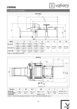
Page 64: ...60 82 3265mm 128 54 2880mm 113 38 2685mm 105 7 2460mm 96 85 Omnia 100 4370mm 172 3515mm 138 4 3130mm 123 23 2935mm 115 55 2710mm 106 7 Note L5 hypothetical measure Up View Modello W W1 W2 W3 X Y Z Omn...

Page 65: ......

Page 66: ...002695 rev 02...

Reviews: