Valcom V-2926 User Manual Download Page 6

6

947213

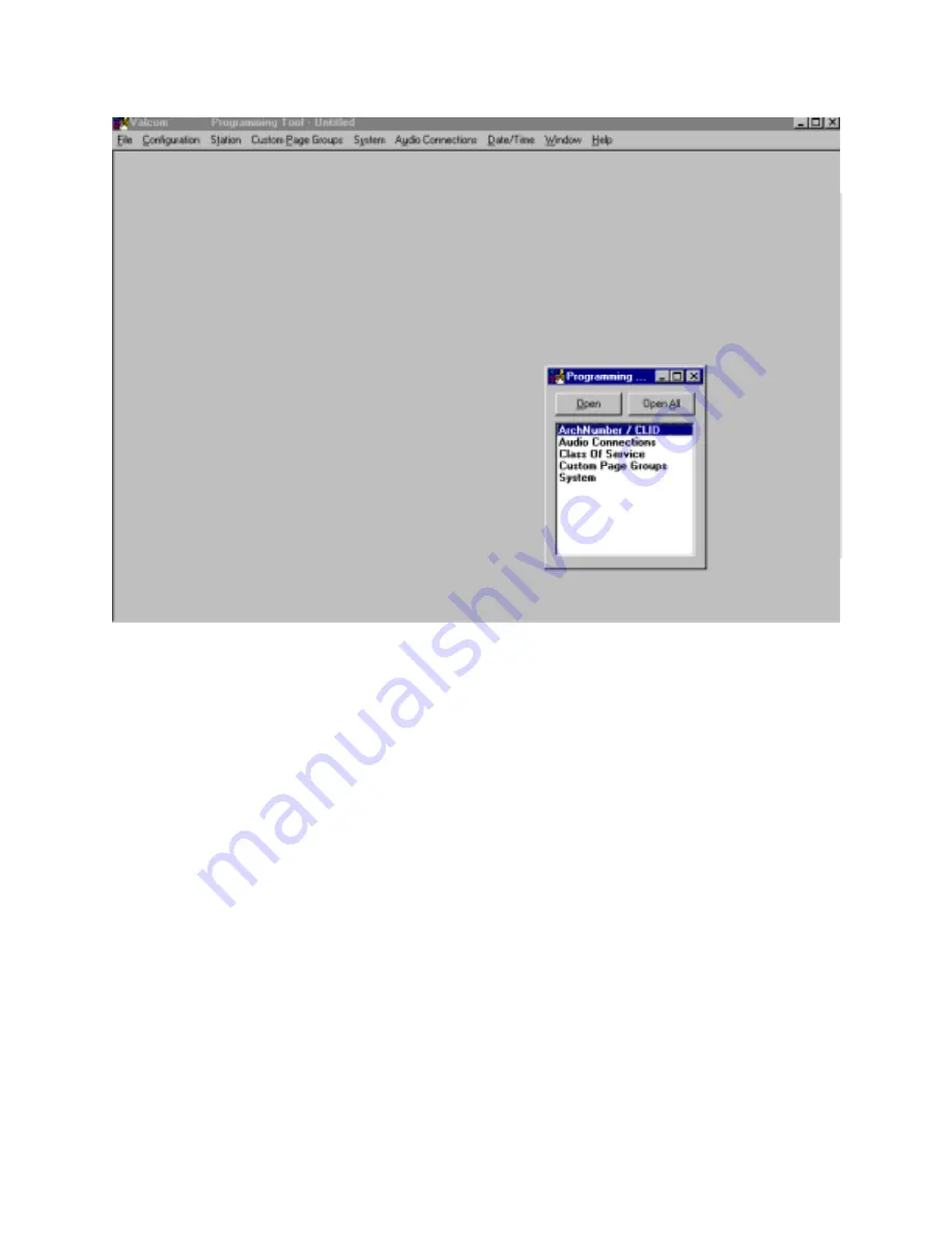
Architectural Number and CLID (Caller ID) Programming

The first function to configure is the 

Architectural Number and CLID Programming

.

The 

Architectural Number

 is a 1 to 4 digit number that is dialed by the phone to connect to a specific speaker.

Flexible architectural numbering is often selected to allow speakers and room numbers to match.  The 

CLID

Programming

 allows a name or up to 15 character description to be entered for each station.

The information entered in the CLID description field will be displayed on the phone or Caller ID unit if provided as
part of the system.

The 

Edit Station Entry

 allows a CLID description to be entered for each station.  Example:  

105

  would be the

Arch # and  

MR. HALL

  would be the CLID description (15 character limit).

The 

Delete Station Entry

 allows removal of selected architectural and CLID descriptions.

Auto Numbering

 assigns the Arch # in sequential order.  The beginning number is the currently selected station; an

ending number must be specified.

To Auto Number – Highlight station where architectural numbering begins.

Select 

Edit Station Entry

.  Enter beginning architectural number and select OK.

Select 

Auto Numbering

 and enter last architectural number (must be a higher number).

Select 

OK

.

Enter information for the Main Board as well as each Expansion Unit being used and press 

OK

 to accept.

V-2924A

Summary of Contents for V-2926

Page 1: ...oard The Option Board and the Programming Tool must both be installed to access the additional features provided by the Option Board All features must be set with the Programming Tool when the Option...

Page 2: ...mming Tool to access the various features it provides INSTALLATION OF THE PROGRAMMING TOOL Minimum Computer Requirements for the Valcom V 2924A Programming Tool Hardware 80486 higher is recommended Ha...

Page 3: ...Board directly over JP2 on the Control Board Press Option Board firmly into place FIGURE 1 OPTION BOARD LOCATION ON THE CONTROL BOARD Side View Top View P10 P1 RS232 Serial Port for SMDR DB9 Connecto...

Page 4: ...uctions assume a New configuration file is being created Click on New from the pull down menu A System Configuration screen is displayed to allow selection of the installed components within the syste...

Page 5: ...Programming Window allows each option to be accessed by selecting the option and pressing Open or by double clicking on the selected option All functions can be listed at once by pressing Open All Al...

Page 6: ...art of the system The Edit Station Entry allows a CLID description to be entered for each station Example 105 would be the Arch and MR HALL would be the CLID description 15 character limit The Delete...

Page 7: ...22 23 24 Main Board Group 5 Stations 25 26 27 28 29 30 Expansion 1 Group 6 Stations 31 32 33 34 35 36 Expansion 1 Group 7 Stations 37 38 39 40 41 42 Expansion 1 Group 8 Stations 43 44 45 46 47 48 Exp...

Page 8: ...queue as they are made 1 button press from the station the call is received as a normal call 4 button presses from the station the call is received as an emergency call Normal Only Calls from station...

Page 9: ...elect OK after all desired page groups are defined System Next select System from the Programming Window A check in the box means ON selected an empty box means OFF not selected Select the desired opt...

Page 10: ...10 947213 Dip switch equivalent of programmed options...

Page 11: ...he V 2924A System This communication can be accomplished through two methods Initiating Communications Direct Connect PC is on site with the V 2924A System can be accessed via RS232 cable To Connect C...

Page 12: ...From the Programming Tool select File Modem and then Modem Connect The screen below appears Enter the number to dial or select a phone number from the list displayed Numbers can be added edited or del...

Page 13: ...be sent to the V 2924A System If no file is open when Send Data to V 2924A is selected the screen appears to allow selection of the data file to be opened and downloaded to the V 2924A Highlight the d...

Page 14: ...c DST Adjustment can be enabled or disabled here Read Software and Firmware Revision Numbers This feature is accessed through the Help menu Select Help then About This option provides information for...

Page 15: ...ns Setup from the File Menu as shown in the following screen display 2 Select Remote Modem Setup and the following screen is displayed 3 If Yes is selected the dip switches at the back of the modem mu...

Page 16: ...t and click OK The program then attempts to test the communication line between the PC and the modem If the connection is okay continue to Step 5 If the connection fails you can Abort the setup Retry...

Page 17: ...e commands to the modem 7 Save the settings to the modem s memory by selecting Yes as shown in the figure below 8 If Yes was selected in step 2 now with the modem power OFF set the dip switches to the...

Page 18: ...en below appears verifying a successful setup MENU OPTIONS PRINT The print option allows the system to provide a hard copy verification of how the system is programmed To print the PC must be connecte...

Page 19: ...ect the screens individually from the pull down window HELP The Help pull down menu provides on screen definition of elements provided by the V 2924A Talkback Intercom System Select Help select Conten...

Page 20: ...ction by Valcom Inc indicates the validity of the claim 2 the defect is not the result of damage misuse or negligence after the original shipment 3 the product has not been altered in any way or repai...

Reviews: