


Rev. 1.2
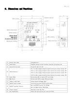
5.Dimensions and Functions
①
Intensity Volume Knob
For digital control
②
Digital Display
Display the setting of the light intensity or the setting of the lighting mode.
③
Channel Selection Switch
Selects CH1, CH2, CH3, CH4.
④
Channel Indicators
CH1 lit: Lit when changing settings for Light Unit connected to output connector CH1.
CH2 lit: Lit when changing settings for Light Unit connected to output connector CH2.
CH3 lit: Lit when changing settings for Light Unit connected to output connector CH3.
CH4 lit: Lit when changing settings for Light Unit connected to output connector CH4.
⑤
Control Switch
Selects internal (INT.) or external (EXT.) control mode.
⑥
Mode Switch
Selects normal (NOR.) or strobe (STR.) control mode.
⑦
Trigger H/L Logic Switch
Selects the logic of the trigger signal.
⑧
External Control Connector
For external control with RS-232C communications.
⑨
External Trigger Input Connector
Inputs the ON/OFF signal for ON/OFF Mode.
Inputs the trigger signal for Strobe Mode.
⑩
Output Connectors
Supply power to the Light Units.
⑪
Input Terminal Block
Connects the power source to the Control Unit DC12V.