background image

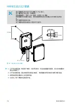
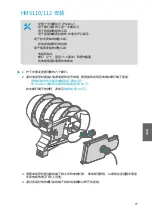
5. 立柱式安装:

a. 使用提供的抱箍和螺钉在柱子上安装变送器。

b. 要防止变送器在柱子上转动,请拧紧抱箍的中心孔上的固定螺钉。 

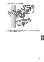
6. 墙面安装:

a. 为壁式插塞钻两个孔,相隔 100 毫米。

b. 将墙壁插塞放入孔中。

c. 使用两个足够长的螺钉安装变送器。 

100 mm

Ø 5.5 mm

78

M211692EN-C

Summary of Contents for hmdw110 series

Page 1: ...EN DE FR JA ZH RU M211692EN C Quick Guide Vaisala Humidity and Temperature Transmitter Series HMDW110...

Page 2: ...inal English versions In ambiguous cases the English versions are applicable not the translations The contents of this document are subject to change without prior notice Local rules and regulations m...

Page 3: ...Table of Contents English 5 Deutsch 21 Fran ais 39 57 73 89 3...

Page 4: ...4 M211692EN C...

Page 5: ...10 series can also supply the operating power to the display using only the loop power from the outputs HMDW110 series transmitters offer several output parameters Relative humidity RH and temperature...

Page 6: ...ing wires 19 mm open end wrench for tightening the cable gland 13 84 250 2 5 2 5 mm Figure 1 HMD110 112 Installation 1 Remove the yellow transport protection cap and separate the fastening flange from...

Page 7: ...re 2 HMD110 112 Centering Inside Duct 5 Secure the transmitter to the flange by tightening the screw on the flange that holds the probe in place 6 Open the transmitter cover and route the cables throu...

Page 8: ...mm open end wrench for tightening the cable gland 88 mm 10 mm 8 mm 3 5 mm 4 8 mm Figure 3 HMW110 112 Installation 1 Open the transmitter cover and use two screws not included to attach the transmitte...

Page 9: ...1 Open the six screws that hold the transmitter cover 2 Route the power and signal cable through the cable gland and connect the wires to the screw terminals according to the wiring instructions Wiri...

Page 10: ...prevent the transmitter from turning on the pole tighten the set screw on the center hole of the clamp 6 Wall installation mounting a Drill two holes for wall plugs 100 mm apart b Place the wall plugs...

Page 11: ...e the cover and tighten the screws 8 Secure the cable to the pole using a zip tie or on the wall using cable clips Allow some cable to hang down from the cable gland to prevent water from entering the...

Page 12: ...p outputs Must be disconnected when the transmitter is powered through RS 485 connection in the lower terminal block terminals 1 4 2 Service port connector 4 pin M8 3 Terminal block for RS 485 output...

Page 13: ...ection The service port is intended for a temporary connection to the transmitter You can use it for configuration calibration and troubleshooting using a computer with Windows operating system Use Va...

Page 14: ...on With HMDW110 transmitters ordered with analog output you must always connect the humidity measurement current loop HUM terminals 5 and 6 to power the transmitter Connecting the temperature measurem...

Page 15: ...8 is optional Connect the RDP100 remote display panel using terminals 1 4 The HMDW110 series transmitter provides both power and data to the RDP100 Terminals 1 4 shall be used only for connecting the...

Page 16: ...mitter DC power supply 4 Pwr 3 Pwr 2 RS485 1 RS485 RS 485 host RS 485 RS 485 RS 485 common 10 28 VDC Figure 9 HMDW110 Wiring Modbus Output Do not connect the analog outputs terminals 5 8 at the same t...

Page 17: ...its of a floating point number are placed at the Modbus register listed in the table while the most significant 16 bits are placed in the register with number address 1 as specified in Open Modbus TCP...

Page 18: ...ut is shown in metric units If non metric values are needed in Modbus use the units shall be converted in the Modbus master PLC using the scaling functions typically available Table 4 Modbus Measureme...

Page 19: ...t Insight from transmitter software version 2 2 3 onwards Connecting to Insight Software Computer with Vaisala Insight software installed USB connection cable order code 219690 Before connecting the t...

Page 20: ...vaisala com support Warranty For standard warranty terms and conditions see www vaisala com warranty Please observe that any such warranty may not be valid in case of damage due to normal wear and tea...

Page 21: ...erden Die Serie HMDW110 kann zudem die Betriebsleistung f r das Anzeigefeld ber die Schleifenleistung der Ausg nge bereitstellen Messwertgeber der Serie HMDW110 besitzen verschiedene Ausgabeparameter...

Page 22: ...von Kabeln 19 mm Gabelschl ssel zum Festziehen der Kabelverschraubung 13 84 250 2 5 2 5 mm Abbildung 10 HMD110 112 Montage 1 Entfernen Sie die gelbe Transportschutzkappe und bauen Sie den Befestigungs...

Page 23: ...im Rohr 5 Befestigen Sie den Messwertgeber am Flansch indem Sie die Schraube die die Sonde in Position h lt am Flansch festziehen 6 ffnen Sie die Abdeckung des Messwertgebers und leiten Sie die Kabel...

Page 24: ...belschl ssel zum Festziehen der Stopfbuchsenverschraubung 88 mm 10 mm 8 mm 3 5 mm 4 8 mm Abbildung 12 HMW110 112 Montage 1 ffnen Sie das Geh use des Messwertgebers und befestigen Sie den Messwertgeber...

Page 25: ...die sechs Schrauben der Abdeckung des Messwertgebers 2 F hren Sie Strom und Signalkabel durch die Kabeldurchf hrung und schlie en Sie die Dr hte gem der Verdrahtungsanleitung an die Schraubklemmen an...

Page 26: ...Einstellschraube in der mittleren Bohrung der Schelle fest um zu verhindern dass sich der Messwertgeber am Rohrmast dreht 6 Befestigung an der Wand a Bohren Sie zwei D bell cher in einem Abstand von...

Page 27: ...ziehen Sie die Schrauben fest 8 Befestigen Sie das Kabel mit einem Kabelbinder am Rohrmast oder mit Kabelklemmen an der Wand Lassen Sie etwas Kabel von der Kabeldurchf hrung nach unten h ngen um zu ve...

Page 28: ...uss getrennt werden wenn der Messwertgeber ber die RS 485 Verbindung im unteren Klemmenblock Klemmen 1 4 gespeist wird 2 Serviceschnittstellenanschluss 4 polig M8 3 Klemmenblock f r RS 485 Ausgang F r...

Page 29: ...elle ist f r tempor re Verbindungen zum Messwertgeber gedacht Sie kann f r Konfiguration Kalibrierung und Fehlerdiagnose mit einem Computer mit Windows Betriebssystem verwendet werden Verwenden Sie di...

Page 30: ...die HMDW110 Messwertgeber mit Analogausgang bestellt werden m ssen Sie die Stromschleife f r die Feuchtemessung HUM Klemmen 5 und 6 zum Speisen des Messwertgebers verwenden Das Anschlie en der Stroms...

Page 31: ...ptional Verbinden Sie das Fernanzeigefeld RDP100 mit den Klemmen 1 4 Der Messwertgeber der Serie HMDW110 speist Strom und Daten in das RDP100 Die Klemmen 1 4 d rfen bei Verwendung der Analogausg nge n...

Page 32: ...orgung 4 Pwr 3 Pwr 2 RS485 1 RS485 RS 485 Host RS 485 RS 485 RS 485 Masse 10 28 VDC Abbildung 18 HMDW110 Verdrahtung Modbus Ausgang Verbinden Sie die Analogausg nge Klemmen 5 8 nicht gleichzeitig wenn...

Page 33: ...Genauigkeit bezeichnet codiert Die niederwertigen 16 Bits einer Gleitkommazahl werden in dem in der Tabelle angegebenen Modbus Register abgelegt w hrend die 16 h chstwertigen Bits im Register mit der...

Page 34: ...in metrischen Einheiten angezeigt Wenn bei Verwendung von Modbus nicht metrische Werte ben tigt werden sind die Einheiten im Modbus Master SPS mit den blicherweise verf gbaren Skalierungsfunktionen zu...

Page 35: ...hmen Die Software Insight k nnen Sie unter www vaisala com insight herunterladen HMDW110 Messwertgeber unterst tzen Insight ab Softwareversion 2 2 3 Verbindung mit der Software Insight Computer auf de...

Page 36: ...s Insight den Messwertgeber erkannt hat Wenn der Messwertgeber nicht erkannt wird ziehen Sie das Vaisala USB Kabel von der Serviceschnittstelle des Messwertgebers ab und stecken Sie es dann wieder ein...

Page 37: ...ere Standardgarantiebedingungen finden Sie unter www vaisala com warranty Diese Garantie deckt keine Verschlei sch den Sch den infolge au ergew hnlicher Betriebsbedingungen Sch den infolge unzul ssige...

Page 38: ...38 M211692EN C...

Page 39: ...a pour un affichage des mesures en temps r el La s rie HMDW110 peut galement fournir l alimentation de fonctionnement pour l cran gr ce l alimentation par la boucle Les transmetteurs de la s rie HMDW1...

Page 40: ...La fiche technique et le guide de l utilisateur en anglais de la s rie HMDW110 sont disponibles sur la page du produit l adresse www vaisala com hmdw110 40 M211692EN C...

Page 41: ...s fils Cl plate de 19 mm pour serrer le presse toupe 13 84 250 2 5 2 5 mm Figure 19 Installation du HMD110 112 1 Retirez le capuchon de protection de transport jaune et s parez la bride de fixation du...

Page 42: ...10 112 l int rieur de la conduite 5 Fixez le transmetteur sur la bride en serrant la vis de la bride qui maintient la sonde en place 6 Ouvrez le couvercle du transmetteur et faites passer les c bles d...

Page 43: ...et d nuder les fils Cl plate de 19 mm pour serrer le presse toupe 88 mm 10 mm 8 mm 3 5 mm 4 8 mm Figure 21 Installation du HMW110 112 1 Ouvrez le couvercle et utilisez deux vis non fournies pour fixe...

Page 44: ...ennent le couvercle du transmetteur 2 Faites passer le c ble d alimentation et de signal par le presse toupe puis connectez les c bles aux borniers vis en respectant les instructions de c blage Dispos...

Page 45: ...her le transmetteur de tourner sur le m t serrez la vis d arr t dans l orifice central du collier 6 Montage de l installation murale a Percez deux orifices s par s de 100 mm pour les chevilles b Place...

Page 46: ...ercle et serrez les vis 8 Fixez le c ble au m t l aide d une attache autobloquante ou au mur l aide de serre c bles Laissez pendre du c ble du presse toupe afin d viter que de l eau n entre dans le tr...

Page 47: ...boucle de courant 4 20 mA Doit tre d connect lorsque le transmetteur est aliment par la connexion RS 485 dans le bornier inf rieur bornes 1 4 2 Connecteur du port de service M8 4 broches 3 Bornier po...

Page 48: ...ransmetteur Vous pouvez l utiliser pour la configuration l talonnage et le d pannage avec un ordinateur quip du syst me d exploitation Windows Utilisez le logiciel Vaisala Insight pour vous connecter...

Page 49: ...MDW110 Pour les transmetteurs HMDW110 avec sortie analogique vous devez toujours connecter la boucle de courant de mesure d humidit HUM bornes 5 et 6 pour alimenter le transmetteur La connexion de la...

Page 50: ...tez l cran d affichage distant RDP100 avec les bornes 1 4 Le transmetteur de la s rie HMDW110 fournit la fois l alimentation et les donn es au RDP100 Les bornes 1 4 doivent tre utilis es uniquement po...

Page 51: ...Alimentation lectrique CC 4 Pwr 3 Pwr 2 RS485 1 RS485 H te RS 485 RS 485 RS 485 RS 485 commun 10 28 VCC Figure 27 C blage du HMDW110 sortie Modbus Ne raccordez pas les sorties analogiques bornes 5 8...

Page 52: ...s 16 bits les moins significatifs d un nombre virgule flottante sont plac s dans le registre Modbus indiqu dans le tableau tandis que les 16 bits les plus significatifs sont plac s dans le registre av...

Page 53: ...t s m triques Si des valeurs non m triques sont n cessaires lors de l utilisation de Modbus les unit s sont converties dans le ma tre Modbus PLC l aide des fonctions de mise l chelle g n ralement disp...

Page 54: ...se www vaisala com insight Les transmetteurs HMDW110 prennent en charge Insight partir de la version logicielle 2 2 3 du transmetteur Connexion au logiciel Insight Ordinateur avec le logiciel Vaisala...

Page 55: ...m support Garantie Pour conna tre nos conditions de garantie standard rendez vous sur la page www vaisala com warranty Veuillez noter qu une telle garantie ne s applique pas en cas de dommage d l usur...

Page 56: ...56 M211692EN C...

Page 57: ...MW110 112 HMS110 112 HMDW110 2 Modubs RS 485 Modbus RTU HMD112 HMW112 HMS112 HMD110 HMW110 HMS110 Modbus RTU RDP HMDW110 RDP100 HMDW110 RH T 13 HMDW110 T C F RH Td f C F 0 C Tf h kJ kg BTU lb Tw C F H...

Page 58: ...HMD110 112 Pozidriv 2 5 mm 13 mm 19 mm 13 84 250 2 5 2 5 mm 28 HMD110 112 1 2 3 2 58 M211692EN C...

Page 59: ...4 29 HMD110 112 5 6 7 59...

Page 60: ...HMW110 112 Pozidriv 2 3 5 mm 8 mm 19 mm 88 mm 10 mm 8 mm 3 5 mm 4 8 mm 30 HMW110 112 1 2 2 3 4 60 M211692EN C...

Page 61: ...HMS110 112 Pozidriv 19 mm 2 5 5 m 1 6 2 66 Modbus 68 64 3 4 61...

Page 62: ...5 a b 6 a 2 100 mm b c 2 100 mm 5 5 mm 62 M211692EN C...

Page 63: ...7 8 63...

Page 64: ...HMDW110 2 Modbus RS 485 8 T 7 T 6 HUM 5 HUM 4 Pwr 3 Pwr 2 RS485 1 RS485 Service Port 1 2 3 31 HMDW110 1 4 20 mA 1 4 RS 485 2 4 M8 3 RS 485 Modbus RDP100 RS 485 Modbus 5 8 Modbus RS 485 64 M211692EN C...

Page 65: ...1 4 RDP100 Modbus RS 485 Windows Vaisala Insight Vaisala USB 219690 RS 485 RS 485 Modbus RDP100 M8 Insight www vaisala com insight Vaisala Insight HMDW110 Series User Guide M211726EN www vaisala com...

Page 66: ...MDW110 10 28 VDC 0 600 VDC 600 0 0 20 28 10 300 32 HMDW110 HMDW110 HUM 5 6 7 8 8 T 7 T 6 HUM 5 HUM A A 2 x 4 20 mA RL 0 600 33 HMDW110 1 8 T 7 T 6 HUM 5 HUM A A 2 x 4 20 mA RL 0 600 34 1 HMDW110 66 M2...

Page 67: ...3 Pwr 2 RS485 1 RS485 A A RDP100 HMDW110 10 28 VDC 10 28 VDC 2 x 4 20 mA RL 0 600 PWR GND RS485 RS485 GND ExtPWR 35 RDP100 HMDW110 HUM 5 6 7 8 1 4 RDP100 HMDW110 RDP100 1 4 RDP100 RDP100 1 4 RDP100 GN...

Page 68: ...Modbus Modbus 1 4 RS 485 RS 485 HMDW110 DC 4 Pwr 3 Pwr 2 RS485 1 RS485 RS 485 RS 485 RS 485 RS 485 10 28 VDC 36 HMDW110 Modbus Modbus 1 4 5 8 68 M211692EN C...

Page 69: ...us 14 Modbus 19200 N 8 2 Modbus 240 0 Modbus RTU Modbus Vaisala Insight Insight www vaisala com insight 32 IEEE 754 binary32 Open Modbus TCP Specification Release 1 0 16 Modbus 16 1 Modicon Modbus 793...

Page 70: ...10 16 7938 1F01hex 32 123 45 7940 1F03hex 7 ASCII 123 45 quiet NaN Modbus Modbus PLC 16 Modbus 10 16 1 0000hex 32 RH 3 0002hex 32 C 9 0008hex 32 C 19 0012hex 32 C 27 001Ahex 32 kJ kg 70 M211692EN C...

Page 71: ...219690 Insight Insight Insight HMDW110 HMDW110 Series User Guide M211726EN Insight www vaisala com insight HMDW110 2 2 3 Insight Insight Vaisala Insight USB 219690 PC 5 8 64 1 4 RDP100 Modbus RS 485...

Page 72: ...helpdesk vaisala com www vaisala com support www vaisala com warranty 72 M211692EN C...

Page 73: ...2 HMW110 112 HMS110 112 HMDW110 2 RS 485 Modbus RTU HMD112 HMW112 HMS112 HMD110 HMW110 HMS110 Modbus RTU RDP100 HMDW110 HMDW110 RH T RH T 17 HMDW110 T C F RH Td f C F 0 C Tf h kJ kg BTU lb Tw C F HMDW...

Page 74: ...HMD110 112 Pozidriv 2 5 13 19 13 84 250 2 5 2 5 mm 37 HMD110 112 1 2 3 Vaisala 74 M211692EN C...

Page 75: ...4 38 HMD110 112 5 6 7 75...

Page 76: ...HMW110 112 Pozidriv 3 5 8 19 88 mm 10 mm 8 mm 3 5 mm 4 8 mm 39 HMW110 112 1 2 3 4 76 M211692EN C...

Page 77: ...HMS110 112 Pozidriv 19 2 5 5 1 2 82 Modbus 84 80 3 4 77...

Page 78: ...5 a b 6 a 100 b c 100 mm 5 5 mm 78 M211692EN C...

Page 79: ...7 8 79...

Page 80: ...S 485 8 T 7 T 6 HUM 5 HUM 4 Pwr 3 Pwr 2 RS485 1 RS485 Service Port 1 2 3 40 HMDW110 1 4 20 mA 1 4 RS 485 2 4 M8 3 RS 485 Modbus RDP100 RS 485 Modbus 5 8 Modbus RS 485 PC 5 8 80 1 4 RDP100 Modbus RS 48...

Page 81: ...Windows Vaisala Insight USB 219690 RS 485 RS 485 Modbus RDP100 M8 www vaisala com insight Insight Vaisala Insight HMDW110 Series User Guide M211726EN www vaisala com hmdw110 81...

Page 82: ...HMDW110 10 28 VDC 0 600 VDC 600 0 0 20 28 10 300 41 HMDW110 HMDW110 HUM 5 6 7 8 8 T 7 T 6 HUM 5 HUM A A 2 x 4 20 mA R L 0 600 42 HMDW110 8 T 7 T 6 HUM 5 HUM A A 2 x 4 20 mA R L 0 600 43 HMDW110 82 M21...

Page 83: ...Pwr 2 RS485 1 RS485 A A RDP100 HMDW110 10 28 VDC 10 28 VDC 2 x 4 20 mA RL 0 600 PWR GND RS485 RS485 GND ExtPWR 44 HMDW110 RDP100 HUM 5 6 7 8 1 4 RDP100 HMDW110 RDP100 1 4 RDP100 RDP100 1 4 RDP100 GND...

Page 84: ...Modbus 1 4 Modbus RS 485 RS 485 HMDW110 4 Pwr 3 Pwr 2 RS485 1 RS485 RS 485 RS 485 RS 485 RS 485 10 28 VDC 45 HMDW110 Modbus Modbus 1 4 5 8 84 M211692EN C...

Page 85: ...00 N 8 2 Modbus 240 0 Modbus RTU Vaisala Insight Modbus www vaisala com insight Insight 32 IEEE 754 binary32 Modbus TCP 1 0 16 Modbus 16 1 little endian Modicon 7938 Modbus Modbus 19 Modbus 7937 1F00h...

Page 86: ...NaN Modbus Modbus PLC 20 Modbus 1 0000hex 32 RH 3 0002hex 32 C 9 0008hex 32 C 19 0012hex 32 C 27 001Ahex 32 kJ kg 86 M211692EN C...

Page 87: ...690 Insight Insight Insight HMDW110 HMDW110 Series User Guide M211726EN www vaisala com insight Insight HMDW110 2 2 3 Insight Insight Vaisala Insight USB 219690 PC 5 8 80 1 4 RDP100 Modbus RS 485 1 In...

Page 88: ...Vaisala helpdesk vaisala com www vaisala com support www vaisala com warranty 88 M211692EN C...

Page 89: ...110 HMDW110 HMD110 112 HMW110 112 HMS110 112 HMDW110 RS 485 Modbus RTU HMD112 HMW112 HMS112 HMD110 HMW110 HMS110 Modbus RTU Vaisala RDP100 HMDW110 HMDW110 RH T RH T 21 HMDW110 T C F RH Td f C F 0 C Tf...

Page 90: ...Tw C F HMDW110 www vaisala com hmdw110 90 M211692EN C...

Page 91: ...HMD110 112 Pozidriv 2 5 13 19 13 84 250 2 5 2 5 mm 46 HMD110 112 1 2 3 91...

Page 92: ...4 47 HMD110 112 5 6 7 92 M211692EN C...

Page 93: ...HMW110 112 Pozidriv 3 5 8 19 88 mm 10 mm 8 mm 3 5 mm 4 8 mm 48 HMW110 112 1 2 3 4 93...

Page 94: ...HMS110 112 Pozidriv 19 2 5 5 1 2 99 Modbus 101 97 3 4 94 M211692EN C...

Page 95: ...5 a b 6 a 100 b c 100 mm 5 5 mm 95...

Page 96: ...7 8 96 M211692EN C...

Page 97: ...HMDW110 Modbus RS 485 8 T 7 T 6 HUM 5 HUM 4 Pwr 3 Pwr 2 RS485 1 RS485 Service Port 1 2 3 49 HMDW110 1 4 20 RS 485 1 4 2 4 M8 3 RS 485 Modbus RDP100 RS 485 Modbus 5 8 RS 485 Modbus 97...

Page 98: ...100 Modbus RS 485 Windows Vaisala Insight USB Vaisala 219690 RS 485 Modbus RS 485 RDP100 M8 Insight www vaisala com insight Vaisala Insight HMDW110 Series User Guide M211726EN www vaisala com hmdw110...

Page 99: ...HMDW110 HMDW110 10 28 0 600 600 0 0 20 28 10 300 50 HMDW110 HMDW110 HUM 5 6 7 8 8 T 7 T 6 HUM 5 HUM A A 2 x 4 20 RL 0 600 51 HMDW110 8 T 7 T 6 HUM 5 HUM A A 2 x 4 20 RL 0 600 52 HMDW110 99...

Page 100: ...Pwr 2 RS485 1 RS485 A A RDP100 HMDW110 10 28 10 28 2 x 4 20 RL 0 600 PWR GND RS485 RS485 GND ExtPWR 53 HMDW110 RDP100 HUM 5 6 7 8 RDP100 1 4 HMDW110 RDP100 1 4 RDP100 RDP100 1 4 GND RDP100 3 HMDW110 R...

Page 101: ...Modbus 1 4 Modbus RS 485 RS 485 HMDW110 4 3 2 RS485 1 RS485 RS 485 RS 485 RS 485 RS 485 10 28 54 HMDW110 Modbus 5 8 Modbus 1 4 101...

Page 102: ...s Modbus Modbus RTU Modbus RS 485 22 Modbus 19200 N 8 2 Modbus 240 0 Modbus RTU Vaisala Insight Modbus Insight www vaisala com insight 32 32 IEEE 754 16 Modbus 16 1 Open Modbus TCP 1 0 Modicon 7938 Mo...

Page 103: ...Modbus 23 Modbus 7937 1F00 16 12345 7938 1F01 32 123 45 7940 1F03 ASCII 7 123 45 quiet NaN Modbus Modbus 24 Modbus 1 0000 32 3 0002 32 C 9 0008 32 C 19 0012 32 C 27 001A 32 103...

Page 104: ...nsight USB Vaisala 219690 Insight Insight HMDW110 Series User Guide M211726EN HMDW110 Insight www vaisala com insight HMDW110 Insight 2 2 3 Insight Vaisala Insight USB 219690 5 8 97 1 4 RDP100 Modbus...

Page 105: ...3 USB 4 Insight USB Vaisala 105...

Page 106: ...Vaisala helpdesk vaisala com www vaisala com support www vaisala com warranty 106 M211692EN C...

Page 107: ......

Page 108: ...www vaisala com...

Reviews: