background image

13

Operating and Installation Manual for uniSTOR, auroSTOR, geoSTOR Cylinders 0020080043_00

1

2

3

4

6

7

5

Fig. 5.12  Installing the safety groups

Key to Fig. 5.12

1 Venting 

knob

2 Blow-off 

line

3 Stop 

valve

4  Stop valve with hand wheel
5 Test 

plug

6  Pressure gauge connection point
7 Backflow 

preventer

6 Start-up

Once installation is complete, the cylinder must be filled 
on the heating and DHW sides. Proceed as follows to do 
this:
•  VIH S only: Fill the solar circuit (see System Manual).
•  Fill the heating side via the boiler filling and draining 

connection.

•  Check the cylinder and system for leaks.
•  Fill the DHW system via the cold water inlet and bleed 

the system at a hot water draw-off point.

•  Check the function and correct setting of all control 

and monitoring devices.

•  Program the timer or timer program, if present, on 

the controller (define the start of the enable time for 
cylinder charging).

•  Put the boiler into operation.
•  VIH S only: Put the solar system into operation.

6.1 Regulations

Observe all applicable national regulations and guide-
lines.
Before the installation, check if there are further local 
regulations.

7 Maintenance

7.1 

Cleaning the internal tank

Make sure the cleaning devices and cleaning agents are 
in a hygienic condition, since the cleaning work is car-
ried out in the inner tank of the cylinder within the 
drinking water area.
Proceed as follows when cleaning the inner tank:
• Drain the cylinder.
•  Remove the flange cover on the cleaning eye.
•  Clean the cylinder with a jet of water. If necessary, 

loosen any deposits with a suitable tool e.g. a wood or 
plastic scraper and flush them out.

h

 Note!

Ensure that the enamelling of the heating coil 
and the inner tank is not damaged during the 
cleaning work.

•  Replace the flange cover with its associated gaskets 

on the cleaning eye of the cylinder.

• Tighten the screws.

h

 Note!

You must replace any old or damaged seals.

•  Fill the cylinder and check for leaks.

H

 Danger!

Risk of being scalded by hot water! 
The blow-off line on the expansion relief valve 
fitted to the DHW cylinder must remain open at 
all times.
Check the function of the expansion relief valve 
during servicing by venting it.
If this is not done, the possibility of the cylin-
der bursting cannot be ruled out!

7.2 

Servicing the magnesium sacrificial anode

The cylinder is fitted with a magnesium sacrificial anode 
which has an average service life of approx. 5 years.
To service the anode, the plastic cover must be re-
moved and the anode released with a 27 mm AF box 
spanner or socket.

Visual inspection

•  Remove the magnesium sacrificial anode (

1

) and check 

it for erosion.

Installation 5

Start-up 6

Maintenance 7

Summary of Contents for uniSTOR

Page 1: ...ting and Installation Manual uniSTOR auroSTOR geoSTOR Bivalent DHW Cylinder for Solar Systems DHW Cylinder for Heating Systems DHW Cylinder for Heat Pumps VIH S 300 VIH S 400 VIH S 500 VIH R 300 VIH R...

Page 2: ...r service 14 9 2 Manufacturer s warranty 14 10 Technical data 15 10 1 Technical data for VIH S 300 400 500 and VIH R 300 400 500 15 10 2 Technical data for VIH RW 300 16 Operating and Installation Man...

Page 3: ...the cylinder The standby volume for post heating is about a third of the cylinder volume 2 2 Conformity with Directives We confirm that our product is manufactured in accord ance with the EU Pressure...

Page 4: ...rmance data will have to be taken into consideration This unit is not intended for use by persons including children with physical sensory or mental impairments or who have inadequate experience and o...

Page 5: ...ment with an approved qualified servicing company d Danger The operational reliability of the appliance can be impaired resulting in damage to property or personal injury if inspections or maintenance...

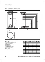
Page 6: ...low R1 5 Pocket for heating sensor 12 6 Heating return R1 7 Circulation connection R3 4 8 Solar flow R1 9 Pocket for solar sensor 12 10 Solar return R1 11 Cold water connection R1 Type Units VIH S 300...

Page 7: ...ction opening 120 3 Hot water connection R1 4 Circulation connection R3 4 5 Heating flow R1 6 Pocket for heating sensor 12 7 Heating return R1 8 Cold water connection R1 Type Units VIH R 300 VIH R 400...

Page 8: ...ection dimensions VIH RW Key to Fig 5 4 2 Inspection opening 120 3 Hot water connection R1 4 Heating flow R1 5 Circulation connection R3 4 6 Pocket for heating sensor 12 7 Heating return R1 8 Cold wat...

Page 9: ...ove and refit the casing and insulation takes 1 person approx 10 minutes Note The installation can optionally be carried out with or without the insulation casing Note If necessary use the transport a...

Page 10: ...ion the hand cart in front of the pallet and load the cylinder on to it 5 3 3 Transport without cladding 1 Fig 5 7 Removing the top cap and covers Remove the top cap from the cylinder Pull the two cov...

Page 11: ...5 10 Fastening the casing jacket with the clip 5 3 4 Transport without insulation Fig 5 11 Removing the insulation Using a knife separate the adhesive film at the front and rear joints First remove o...

Page 12: ...cessary safe ty devices If the water pressure at the installation location is less than 10 bar a proof tested DN 25 safety group can be used Install a T piece in the cold water pipe between the cylind...

Page 13: ...re in a hygienic condition since the cleaning work is car ried out in the inner tank of the cylinder within the drinking water area Proceed as follows when cleaning the inner tank Drain the cylinder R...

Page 14: ...xisting accessories are disposed of prop erly 8 2 Packaging The specialist company that installed the unit is respon sible for disposing of the transport packaging h Note Please observe the applicable...

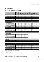
Page 15: ...t water output at a heat ing water temperature of 85 65 C2 kW 20 21 29 46 46 62 Continuous hot water output at a heat ing water temperature of 85 65 C2 l h 491 516 712 1130 130 1523 Output characteris...

Page 16: ...ater demand mbar 124 Heating medium flow l h 2000 Initial hot water output at 10 45 C and a cylinder temperature of 60 C l 10min 410 Continuous hot water output at 10 45 C and a heating water temperat...

Page 17: ......

Page 18: ......

Page 19: ......

Page 20: ...0020080043_00 EXP 062009 Subject to alterations...

Reviews: