


31
Installation Manual recoVAIR/3 0020062918_03
Action
Display
Meaning
3 Sec.
+
BYP
ON
Bypass switches to summer
mode
Turn
ALAR
ON
Alarm output is activated
(contact closed).
Turn
HEAT
ON
Not activated
Turn
SAO/*
xx
o
C
Display of fresh air temperature
(Supply Air Out)
Turn
EAO/
xx
o
C
Display of the discharge air
temperature at the frost pro-
tection sensor (Exhaust Air
Out)
Turn
EAI*
xx
o
C
Display of the exhaust air tem-
perature (Exhaust Air In)
Turn
SAI/*
xx
o
C
Display of the outside air tem-
perature (Supply Air In)
Click
AIR/
xx m
3
/h
Current air volume flow indica-
tion in the ventilation unit. By
turning the dial it is possible to
change the air quantity during
the test mode.
Click
APPL/
3 / 4
Display of the unit type
3 = recoVAIR VAR 275/3
4 = recoVAIR VAR 350/3
Turn the dial to select the unit
type.
Click
Display
Display test: All symbols of the
display are indicated, however,
not all symbols of recoVAIR
have a meaning.
Click
VER1/
x.xx
Display of the software version
of the remote control
Turn
VER2/
x.xx
Display of the software version
of the recoVAIR PCB
Return to basic display
Table 5.2 Functions of the service/diagnostics level
* These values can only be called with a bypass unit in-
stalled.
5.1.3
Testing of the bypass and other functions
Go to the service/diagnostics level as described in
section 5.1.2. Now test successively all functions in ac-
cordance with table 5.2. If the bypass is not connected
or if a sensor is defective, the display will show the sym-
bol "-".
5.1.4
Reset to the Factory Setting
• Press the P button for 15 seconds to reset the control-
ler to the default setting.
As soon as the display lights up twice, the controller is
completely re-set to its default settings. This means
that you will have to perform all individual settings
again.
5.1.5
Setting from the Week to the Day Mode
The remote control is factory-set to a week program. It
may be switched if required to the day mode.
• Press the F button for 10 seconds to change the set-
ting of the remote control to day mode.
5.2
Domestic Ventilation Unit Adjustment
5.2.1 Adjustment
procedure
First of all ensure that the overall air flow calculated for
the installation is reached by the system. Then adjust
the air flow rates for the individual living spaces. Then
finally adjust the individual air flow distribution within
each living space.
5.2.2 Total Air Flow Adjustment
First adjust the desired air quantity calculated when the
system was designed with the remote control for all op-
erating modes (installer level). Proceed step by step as
described in table 5.1 in section 5.1.1. In the above-men-
tioned table you will find the information for the desired
values.
h
Note
The planned air flow must be in the in the day
mode (2nd stage) because this is the standard
operation mode.
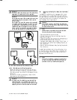
Adjusting the air quantities at the system
1. Adjust all the exhaust and fresh air valves in the living
rooms to the middle opening of about 50 %. Then
proceed in accordance with the instructions given in
the manufacturer operating manual.
The air speed must not exceed 1.5 m/s at a distance of
50 cm from the valve.
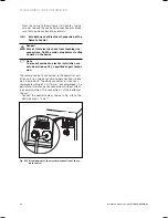
2. Make sure that all valves in the existing air duct mani-
folds are completely opened.
3. Switch the domestic ventilation device into the opera-
tion mode "day mode" using the remote control.
Start-up 5
Summary of Contents for recoVAIR VAR 275/3
Page 2: ......
Page 14: ......
Page 43: ......
Page 44: ...0020062918_03 GB 062009 Subject to alterations ...


