


Installation Manual recoVAIR/3 0020062918_03
20
If the protection circuit is activated against the low
pressure (STOV, see section 5.1.1), the frost protection
sensor switches both ventilators off.
The outside air flow may be much cooler than the tem-
perature of the discharge air measured by the frost pro-
tection sensor before the anti-freeze monitoring device
is activated. Its operation is possible up to -7 °C outside
temperature.
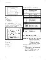
4.3.2 Remote
control
The control elements of the remote control are ex-
plained in the operating manual in section 4.4.
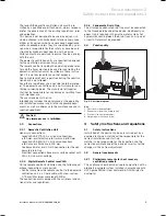
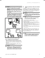
4.3.3 Bypass
1
2
3
Fig. 4.3 Bypass Installation
Key
1 Filter
2 Ventilation
flap
3 Air inlet from outside
Vaillant GmbH Remscheid / Germany
Serial-no. 1234567890xxxxxx
Bypass VAR 275 - VAR 350
12 V DC
P
Max
3
W
IPX2
nur zu verwenden mit recoVAIR 275 / 350
only to use with recoVAIR 275 / 350
alleen te gebruiken met recoVAIR 275 / 350
utiliser seulement avec le recoVAIR 275 / 350
Kan kun bruges sammen med recoVAIR 275/350
Bar – Code
Fig. 4.4 Identification plate Bypass
You can find the identification plate on the top of the
device. The indications given on the identification plate
have the following meaning:
Units
Value
Description
12 V DC
Voltage supply
P
max
3 W
Maximum electrical power consumption
Table 4.1 Explanation of bypass identification plate
4 Assembly and installation
Summary of Contents for recoVAIR VAR 275/3
Page 2: ......
Page 14: ......
Page 43: ......
Page 44: ...0020062918_03 GB 062009 Subject to alterations ...


